5-2SectionConnecting to the Host’s RS-422A/485 Port
110
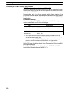
Connecting to a CPM2C
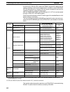
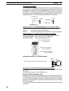
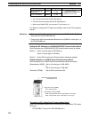
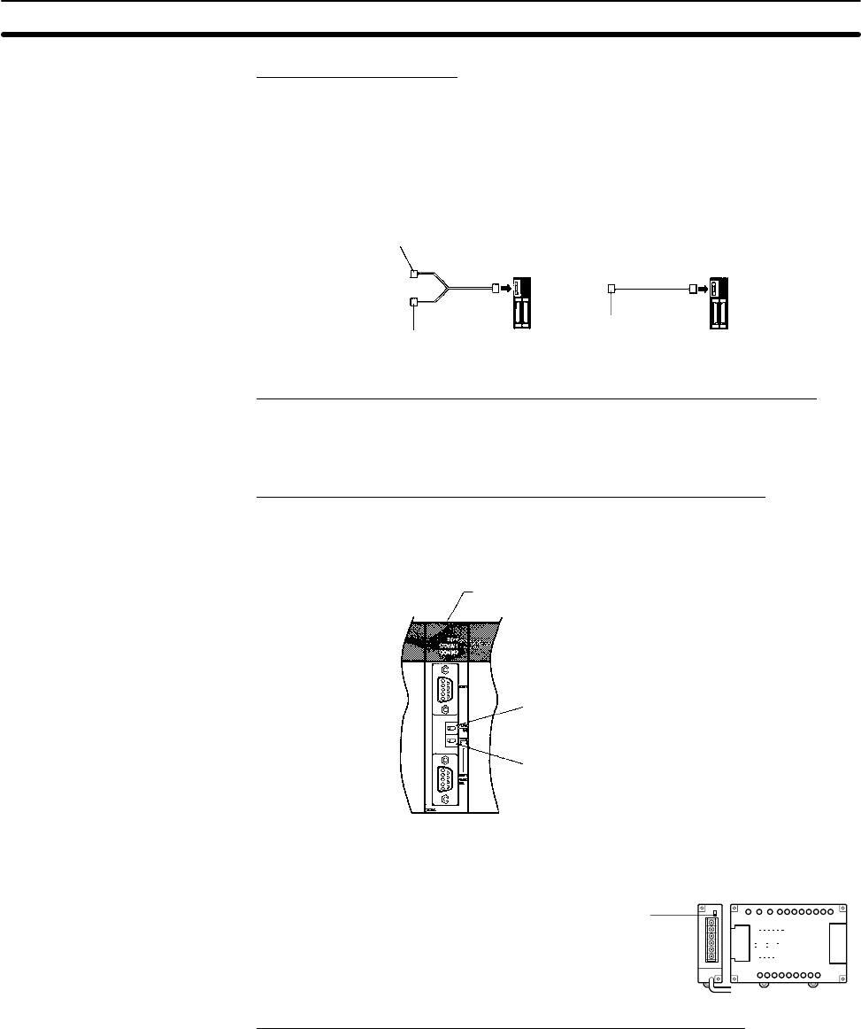
The CPM2C PCs do not have the same kind of port connectors found on
CS1-series PCs. The CPM2C’s communication port handles both RS-232C and
peripheral port connections which are divided internally. Therefore, when using
the CPM2C, it is necessary to select RS-232C or peripheral port connections,
according to the kind of cable and port (on the cable) used, as shown in the fol-
lowing table. Refer to the CPM2C Operation Manual for more details.
Peripheral port
RS-232C port
(D-Sub 9-pin, female)
CPM2C-CN111
CPM2C CPM2C
Peripheral port
CS1W-CN114
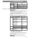
Setting Switches on a C200HX/HG/HE(-Z)E Communications Board
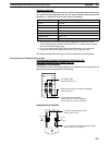
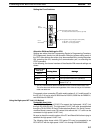
Set the switches on a C200HX/HG/HE(-Z)E communication board as follows.
Switch 1: Set to 4 (4-wire type, for RS-422A)
Switch 2 : Set to ON for terminator ON (termination resistance applied)
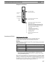
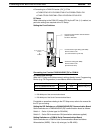
Setting Switches on a CQM1H Serial Communications Board
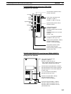
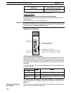
Set the switches on a CQM1H Serial Communications Board as follows.
Wire selection (WIRE): Set to 4 (4-wire type, for RS-422A)
Terminator (TERM): Set to ON for termination ON.
Serial Communications Board
(Inner Board slot 1)
Terminator Switch (TERM)
Set to ON (right side).
Wire Selection Switch (WIRE)
Set to 4 (right side).
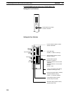
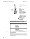
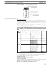
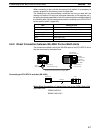
Setting the Switches on an RS-422A Adapter
Set the terminator selector switch to ON (upper position).
CPM1
CPM1-
CIF11
Connecting to a CS1 Series Serial Communications Board
Serial Communications Board with RS-422A/485 port equipped for CS1 series
CPU Type :
CS1W-SCB41 (The port 2 is RS-422A/485 port.)
Allocation DM Area Settings for CPU
Settings are written from the Programming Device (a Programming Console or
CX-Programmer) directly into the allocation DM area (system setting area) of
the CPU. After the settings are written, they become effective by turning the
power ON, restarting the unit, restarting the communication port, or executing
the STUP command.
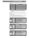
In the following, the channel numbers of the allocation DM area and the settings
are shown.


