


7-1SectionTroubleshooting
234
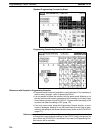
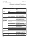
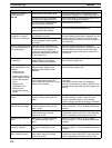
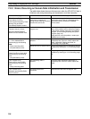
NT31/NT31C Symptoms RemedyCause
Updating of numeric
values and text is
dl d
Malfunction due to external noise Carry out grounding work in accordance with the
conditions by referring to 3-1-4 Grounding, page 34.
delayed.
There are too many numeral/text
displays on the displayed screen.
Reduce the number of numeral/text displays on the
screen for which updating is delayed.
The cycle time is extended due to
heavy processing at the host.
Shorten the host cycle time.
In an RS-422A/485 connection,
there is illegal branching or an
erroneous terminator setting.
Wire correctly by referring to Section 5 Connecting
to the Host from the RS-422A/485 Port.
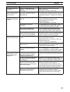
Some of the elements
arranged on a normal
di l d
The quantity of read data exceeds
the stipulated restriction.
Check the maximum number of elements by
referring to Display Restrictions in Appendix A of the
Rf M lCh d i
g
screen are not displayed.
The total of the element coefficients
for the displayed screen is greater
than 1024.
g py pp
Reference Manual. Create the screen data again
and then transmit all of the screen data in a batch to
the NT31/NT31C.
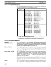
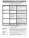
On an overlapping screen,
some of the set elements
are not displayed.
Since the data is transmitted from
the host in screen units, the number
of elements on the overlapping
screen has exceeded the maximum
permissible without being checked
by the Support Tool.
Check the maximum number of elements by
referring to Display Restrictions in Appendix A of the
Reference Manual. Create the screen data again
and then send all the screen data in a batch to the
NT31/NT31C.
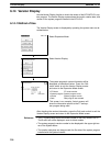
The System Menu cannot
be called up.
Display System Menu under Change
System Settings in the System
Installer mode is set to Disabled.
In the System Installer mode, set Display System
Menu to Enabled (page 153).
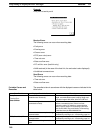
The following System
Menu operations are not
possible.
- Establishing the
Transmit mode
- Displaying the memory
Screen Memory Protect under
Change System Setting in the
System Installer mode is set to
Disabled.
In the System Installer mode, set Screen Memory
Protect to Enabled (page 153).
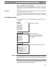
Displaying
the
memory
switch setting screens
- Screen data memory
check
- Displaying the
initialization menu
- Displaying the
calendar/time setting
screen
Screen Memory Protect has been
set to Disabled because the PT
power supply was turned OFF during
deletion of screen data.
Do not turn the PT power OFF during deletion of
screen data.
In the System Installer mode, first change the
setting for Screen Memory Protect to Enabled, then
repeat the screen data delete operation (pages 153
and 154)
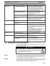
Cannot input numeric
values
The upper/lower (max./min.) limit
check for numeric value input is in
effect.
Check the screen data’s upper/lower (max./min.)
limit check setting for numeric value input, and
correct it if necessary. Refer to 2-12 Inputting
Numeric Values in the Reference Manual for details.
Cannot input numeric
values/character strings.
Bit 5 of the PT status control area
(numeral/character string input) is
set to 1 (ON).
Set bit 5 to 0 (OFF). Refer to 2-2-1 PT Status
Control Area (Host ↔ PT) in the Reference Manual
for details.
The interlock function is set for the
input field and the controlling
interlock bit is OFF.
Inputs are prohibited in input fields when the
corresponding interlock bit is OFF. Check the status
of the corresponding interlock bit and turn it ON.
Window screen does not
open
Bit 6 of the PT status control area
(PT window opening) is set to 1
(ON).
Set bit 6 to 0 (OFF). Refer to 2-2-1 PT Status
Control Area (Host ↔ PT) in the Reference Manual
for details.
Cannot switch screens
with touch switches
Bit 4 of the PT status control area
(PT screen switching) is set to 1
(ON).
Set bit 4 to 0 (OFF). Refer to 2-2-1 PT Status
Control Area (Host ↔ PT) in the Reference Manual
for details.
Touch switch does not
work. (Buzzer sounds.)
The interlock function is set for the
touch switch and the controlling
interlock bit is OFF.
Touch switches are disabled when the
corresponding interlock bit is OFF. Check the status
of the corresponding interlock bit and turn it ON.