


11
-
iRIS 220 / iRIS 320, V1.19 User Guide
Partial Power Save
With the power management mode set to partial save, the on-board LEDs are disabled but the internal
wireless modem remains in the fully active state as with the no power save mode.
Full Power Save
When power management is set to full save mode, the internal LED’s are disabled and the internal wireless
modem remains in a powered off state until a GPRS/CDMA-1X or CSD or SMS session is activated.
NOTE: While the modem is in this state, it is not possible to obtain signal strength measurements or
interrogate the modem via the AT command set using the Modem Terminal mode.
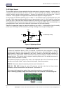
Additional power management features that operate in all modes include:
• Deactivation of RS232 driver ic when the DSR signal is not present.
• Disabling the LCD and turning off the backlight after two minutes of no activity.
• Ability to activate a GPRS/CDMA-1X session at scheduled times of day for pre-set period.
2.8.5 Data Logging
The iRIS supports the logging of data from six virtual sensors, plus a further three internal data sources
(battery voltage, supply voltage and logger temperature). Each of the six virtual sensors can obtain
information from one of the following data sources:
• Analog Input 1
• Analog Input 2
• Analog Input 3
• Analog Input 4
• Pulse Counter attached to Digital Input 1
• Pulse Counter attached to Digital Input 2
• Simulated Pulse Counter enabled by Digital Input 1
• Simulated Pulse Counter enabled by Digital Input 2
• Frequency Counter attached to Digital Input 1
• Frequency Counter attached to Digital Input 2
• Up/down Counter attached to Digital Inputs 1 & 2
• Received Signal Strength Indication (RSSI)
• Internal Database Location (for data obtained via user script or communications link)
• High-speed Serial Instrument (Unidata format)
• SDI-12 serial channel
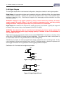
Each sensor can be set up to scale the raw data source into engineering units through the application of a
multiplier and offset (slope and constant). The scaled value can be logged to non-volatile memory at rates
between once per minute to once per hour or on event for pulse inputs. As all logged data is stored in
integer format, a logging multiplier is applied to the scaled value to maintain resolution. See Section
4.3.9.
It is also possible to configure a sensor to also log minimum, maximum, standard deviation or a calculated
flow rate (pulse source only) values. See the next section, Section 2.8.6 and also Section 4.3.9 for further
details on configuring these extended logging features as part of the Sensor Cfg menus.