


43
-
iRIS 220 / iRIS 320, V1.19 User Guide
5.2.4 Display Menu Structure
The actual LCD screens that are available will depend upon the level of access that has been enabled (no
access, not logged-in, or logged-in). The screens available in each mode are shown below:
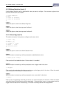
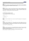
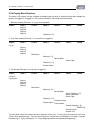
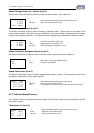
1. Minimum Access (PIN code = 0, Log-in is not possible)
Level 0 Level 1 Level 2 Level 3 Level 4 Level 5 Level6
Status 1
Status 2
Status 3
Status 4
Totalisers [1..2]
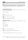
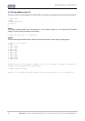
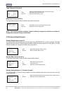
2. View Only Access (PIN code <> 0, but user is not logged-in)
Level 0 Level 1 Level 2 Level 3 Level 4 Level 5 Level6
Log-In
Status 1
Status 2
Status 3
Status 4
Main Menu
Sensors [1..9]
Sensor Menu
Sensor Data
Totalisers [1..2]
Comms Status
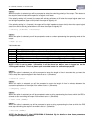
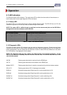
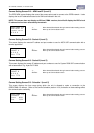
3. Full Access (PIN code <> 0 and user is logged-in)
Level 0 Level 1 Level 2 Level 3 Level 4 Level 5 Level6
Log-In or
Log Control
Status 1
Status 2
Status 3
Status 4
Main Menu
Sensors [1..6]
Sensor Menu
Sensor Settings [1..5]
Sensor Calibration
Sensor Data
Totalisers [1..2]
Totalisers Reset
Comms Status
Comms Menu
Comms Settings [1..9]
RS232 Cfg
Comms Enable
Comms Test
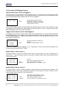
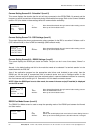
To move down a level in the menu structure, press the <Enter> key. To move up a level press the <Alt> and
<Enter> keys simultaneously. You can loop through the screens that are followed by a number in square
brackets (e.g. [1..4]) by pressing the + or - keys (stepping forwards and backwards respectively).