


55
-
iRIS 220 / iRIS 320, V1.19 User Guide
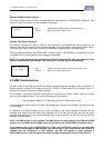
AI4
AI3
AI2
AI1
AGND
5VOP
DI2
DI1
DO2
DO1
SDI-12
DGND
12V+
GND (-)
VIN+
GND (-)
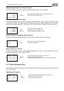
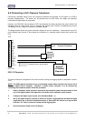
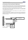
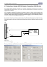
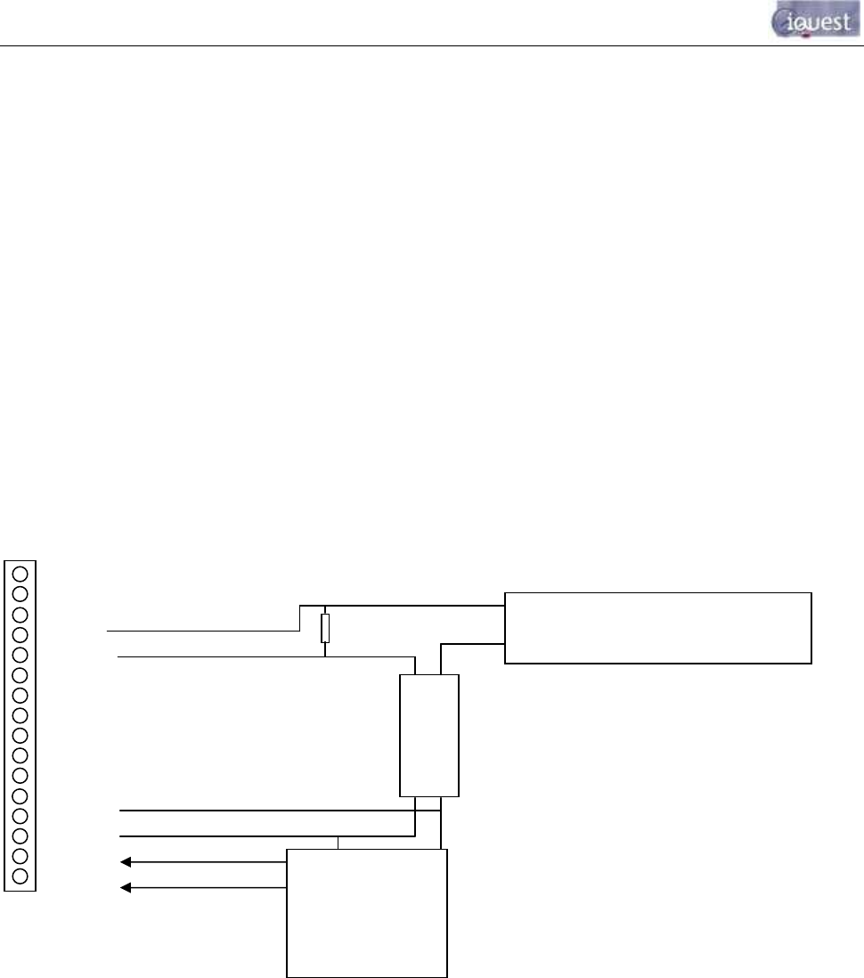
6.3 Connecting a 2-Wire Loop-Powered 4-20mA Sensor
The iRIS 220 /iRIS 320 also supports the connection of many types of industry standard 4-20mA current loop
instruments such as ultrasonic or radar level sensors. A very common configuration used with these devices
is known as two-wire or loop-powered mode. This requires only two wires to the sensor and the 4-20mA loop
current provides power for the sensor as well as being the proportional Analog sensor signal.
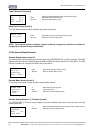
However, theses sensors often require a minimum voltage across them that may not be reliably achieved
with a 12V supply, taking into account the voltage drop across the sense resistor. In such cases, a separate
12-24V boosted sensor supply is recommended.
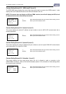
The diagram below shows the recommended connection diagram for such an installation. It assumes the
use of AI1 as the desired input channel.
The 250Ω sense resistor generates a 1-5V signal (from the 4-20mA current), which is then measured at the
Analog input. The sensor should be configured for the correct channel, scaling and logging regime as
described in section 4.3.8. An offset value will be required as part of the configuration, as the 4mA (1V)
offset needs to be eliminated.
TOP
BOTTOM
iRIS I/O Connector
- +
External
12V Battery
(Required)
-
Signal 4-20mA Sensor
+
Isolated
12V – 24V
DC- DC
Converter
- +
24V
12V
-
+
250
Ω
Resistor
Charging source
e.g solar panel