


45
-
iRIS 220 / iRIS 320, V1.19 User Guide
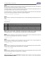
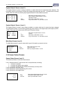
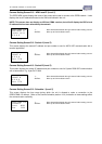
System Status 3 Screen (Level 1)
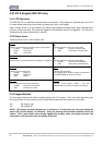
The System Status 3 screen is always available, no matter what level of access has been selected. The
information shown on this screen includes the voltage being measured at the AI1 – AI4 terminals in millivolts.
These values are useful for checking input signals and also for the calibration process.
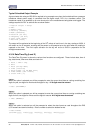
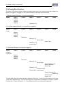
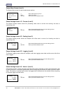
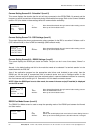
System Status 4 Screen (Level 1)
The System Status 4 screen is also always available, no matter what level of access has been selected.
The information shown on this screen includes the current status of the digital inputs and outputs (0=OFF,
1=ON). This screen shows the current SOD and EOD pointer values.
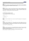
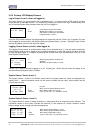
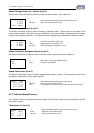
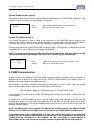
Main Menu Screen (Level 2)
The Main Menu screen is used to select which type of information you want to look at.
5.2.6 Sensor Related Screens
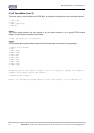
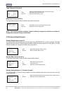
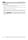
Sensor Status Screen (Level 3)
This screen provides an overview of each sensor.
Line 1 indicates sensor ID, data source and its composite status including:
‘.’ if sensor is enabled
‘:’ if sensor and alarm(s) are enabled
‘*’ if sensor and alarm(s) are enabled and alarm(s) currently active
Line 2 indicates the raw input value.
Line 3 indicates the scaled (engineering unit’s) value.
Line 4 indicates the last logged value.
MAIN MENU
>Sensors
Totals
Comms
1: Bat Volt
→ 1257
← 12.57
↓ 1262
+/- Move down/up through menu
Enter Select menu item
Alt Enter Move up to System Status 1 screen
+/- Move forwards/backwards through sensors
Enter Drill down to Sensor Menu screen
Alt Enter Move up to Main Menu screen
AI1: 1754 mV
AI2: 682 mV
AI3: 1754 mV
AI4: 682 mV
- Move back to System Status 2 screen
+ Move forward to System Status 4 screen
otherwise unused.
Enter Move down to Main Menu screen
Alt Enter Log in (If PIN code <> 0), otherwise unused
DI1:0 DI2:1
DO1:1 DO2:0
SOD: 177104
EOD: 177336
- Move back to System Status 3 screen
+ Unused
Enter Move down to Main Menu screen
Alt Enter Log in (If PIN code <> 0), otherwise unused