


iRIS 220 / iRIS 320, V1.19 User Guide - 46
46
iQuest (NZ) Ltd - PO Box 15169, Hamilton, New Zealand Tel: +64 7 857-0810 Fax: +64 7 857-0811 Email: iquest@iquest.co.nz
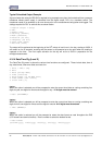
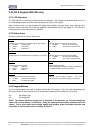
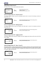
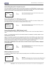
Sensor Menu Screen (Level 4)
The Sensor Menu screen is used to select sensor options.
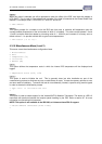
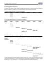
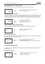
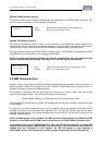
Sensor Settings Screen 1/5 - Process (Level 5)
The Sensor Process screen shows the processing mode used to convert the incoming raw data to
engineering units.
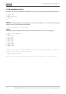
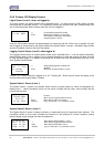
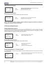
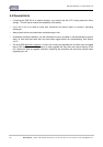
Sensor Settings Screen 2/5 - Scaling (Level 5)
The Sensor Scaling screen shows the multiplier and offset used to convert the incoming raw data to
engineering units.
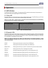
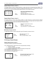
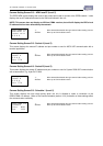
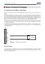
Sensor Settings Screen 3/5 - Logging (Level 5)
The Sensor Logging screen shows the multiplier used when logging sensor data and the rate at which that
data is logged.
Sensor Settings Screen 4/5 - Alarm 1 (Level 5)
Sensor Alarm screen 1 shows the trigger and reset levels used to generate an alarm and the duration used
to qualify the alarm. If the sensor gets its data from an Analog input, the duration is used to provide an alarm
delay. If the sensor is a pulse input counter, the logged data is totalised over the duration before comparing
to the alarm trigger and reset levels.
SENSOR MENU
>Settings
Calibration
Data
SCALING 2/5
x 0.0010
+ 0.0000
LOGGING 3/5
X 00100
∆(min) 00030
ALARM#1 4/5
/ 6.3500
\ 6.5000
∆(min) 00000
+/- Move down/up through menu
Enter Select menu item
Alt Enter Move up to Sensor Status screen
+/- Move forwards/backwards through sensor setting screens.
Alt Enter Move up to Sensor Status screen
+/- Move forwards/backwards through sensor setting screens.
Alt Enter Move up to Sensor Status screen
+/- Move forwards/backwards through sensor setting screens.
Alt Enter Move up to Sensor Status screen
PROCESS 1/5
Mode
Instant
+/- Move forwards/backwards through sensor setting screens.
Alt Enter Move up to Sensor Status screen