


iRIS 220 / iRIS 320, V1.19 User Guide - 20
20
iQuest (NZ) Ltd - PO Box 15169, Hamilton, New Zealand Tel: +64 7 857-0810 Fax: +64 7 857-0811 Email: iquest@iquest.co.nz
4 Configuration
The iRIS configuration is achieved through the connection of a terminal to the internal RS232 serial port.
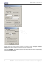
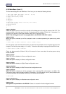
Upon detection of a terminal connection via the DSR signal, the iRIS will output the main configuration menu
to the terminal screen. The following sections describe how to set up a terminal connection and all the menu
options available while connected.
The description assumes a computer running the Microsoft® Windows® operating system is being used and
all examples relate to the standard Windows® terminal emulator application, HyperTerminal™. However,
iQuest also supply iLink, a support utility for configuring the iQuest range of dataloggers and this includes a
terminal emulator that is similar in function to HyperTerminal®. iLink is available from the iQuest website.
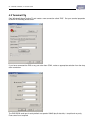
4.1 Terminal Connection
The iRIS RS232 port is a DTE (Data Terminal Equipment) configured port and is identical in pinout and
signal allocation to that of an IBM compatible PC’s RS232 port. Therefore the cable required is the same as
that for computer-to-computer communication and is termed a null-modem cable. These are available from
all good electronic stores if required.
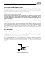
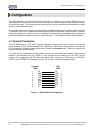
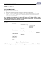
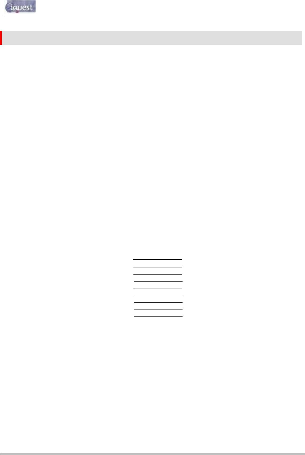
To access the iRIS configuration terminal session, connect a full null-modem cable (wired as shown below)
between a communication port (e.g. COM1) on your computer and the RS232 port of the iRIS. The null
modem cable configuration has the three main signal pairs crossed over. These pairs are TXD/RXD,
RTS/CTS and DTR/DSR. The remaining lines (SG, CD and RI) are connected straight through.
Computer iRIS
DB9F DB9F
1 CD CD 1
2 RXD TXD 3
3 TXD RXD 2
4 DTR DSR 6
5 SG SG 5
6 DSR DTR 4
7 RTS CTS 8
8 CTS RTS 7
9 RI RI 9
Figure 11 - RS232 Cable Pin Designations