


iRIS 220 / iRIS 320, V1.19 User Guide - 16
16
iQuest (NZ) Ltd - PO Box 15169, Hamilton, New Zealand Tel: +64 7 857-0810 Fax: +64 7 857-0811 Email: iquest@iquest.co.nz
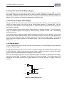
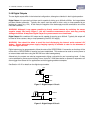
3.4.5 Digital Inputs
The two digital inputs are jumper selectable for either mechanical or electronic operation. In either case it is
necessary to pull the input down to 0Vdc to activate it. Inputs will handle up to 30Vdc in the off state for
parallel connection across existing equipment. Jumpers are positioned to the right hand side of the I/O
connector. The top jumper is for Digital Input #2 and the bottom jumper is for Digital Input #1.
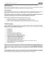
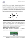
Fit the jumper for mechanical switching at up to 100Hz. In this mode the input is normally pulled up to 12V
through a 10KΩ resistor providing a wetting current of approximately 1.6mA. A 100nF capacitor is also fitted
across the input to provide limited hardware debounce, preventing false triggering due to contact bounce.
For installations that do not have an external power source it is important that the input is not held low for a
prolonged period of time, as this will increase the current drawn from the internal battery.
Remove the appropriate jumper for electronic switching at up to 5kHz. In this mode the input is normally
pulled up to 3.6V through a 57KΩ resistance, providing a wetting current of approximately 60µA.
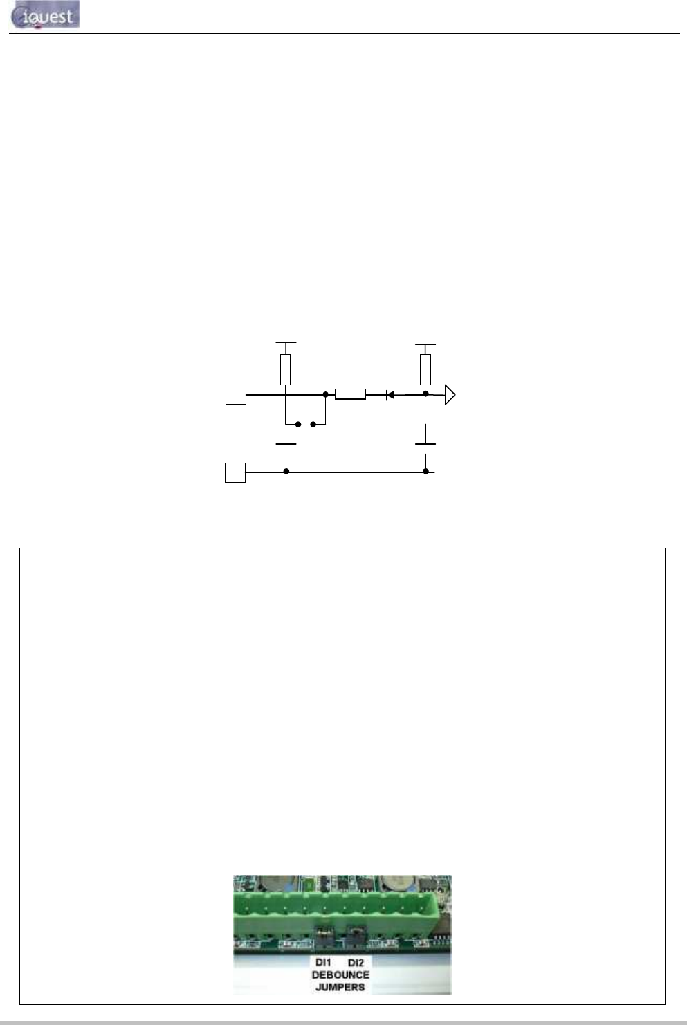
Figure 6 - Digital Input Circuit
IMPORTANT NOTE!
In almost all installations where an iRIS is connected in parallel with other equipment to share a
common pulse input (e.g. from a flow meter), there has not been a detrimental effect, as the iRIS
inputs present a relatively high impedance to the circuit. However, in the event that connecting an
iRIS does cause pulse failure, iQuest recommend removing the debounce selection link for the
appropriate input. This sets the input to electronic switching mode, even if the actual pulse source is
a clean contact (reed switch or similar).
The debounce jumpers are located very close to the right-hand side of the I/O connector and are
therefore not normally visible. To gain access to the jumpers, follow this procedure:
iRIS 220. Remove the electronic assembly from the case. See Section 3.1
iRIS 320 / iRIS 320V. Unplug the green I/O connector and then undo the two hinge screws
completely, so that the enclosure lid can be lifted off. See Section 3.2
Fit or remove the jumpers(s) as required, then reverse the procedure to reassemble the unit.
Hint: If removing a jumper, simply fit it to one pin only of the connector to avoid it being lost.
DINx
DGND
100nF
JPx
4K7
10K
+12V
3V6
1nF
47K
To internal logic circuitry