


3
-
iRIS 220 / iRIS 320, V1.19 User Guide
10 Appendix A – Radio Using the RS232 Interface.......................................................................... 63
11 Appendix B – Voice Annunciation (iRIS 320V)............................................................................ 64
12 Appendix C – SDI-12 (iRIS 320 / 320V only)................................................................................. 65
13 Appendix D – Legacy PCB (Rev 1.1) Details................................................................................ 67
13.1 I/O Connector............................................................................................................................. 67
13.2 Debounce Links ......................................................................................................................... 67
13.3 SDI-12 Interface......................................................................................................................... 68
13.4 Diagnostic LEDs......................................................................................................................... 68
13.5 Transistor Switch........................................................................................................................ 69
14 Appendix E – iRIS 320 Enclosure Material Spec......................................................................... 70
15 Appendix F - Network Settings for iQuest APN or iQuest Global Data Network ..................... 71
Tables / Figures
Table 1- Feature Summary................................................................................................................................ 7
Table 2 - Standard Sensor Sources ................................................................................................................ 32
Table 3 - Internal Sensor Sources................................................................................................................... 32
Table 4 – Supplementary Logging Flag Definitions......................................................................................... 33
Table 5 – Status LED Indication Modes .......................................................................................................... 41
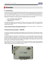
Figure 1 - iRIS 220............................................................................................................................................. 5
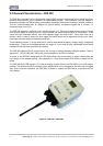
Figure 2 - iRIS 320 / iRIS 320V ......................................................................................................................... 6
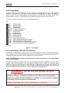
Figure 3 - SIM Carrier...................................................................................................................................... 13
Figure 4 - I/O Connector.................................................................................................................................. 14
Figure 5 - Analog Input Circuit......................................................................................................................... 15
Figure 6 - Digital Input Circuit.......................................................................................................................... 16
Figure 7 - Digital Output 1 Circuit .................................................................................................................... 17
Figure 8 - Digital Output 2 Circuit .................................................................................................................... 17
Figure 9 - iRIS 220 Mounting Diagram............................................................................................................ 18
Figure 10 - iRIS 320 / iRIS 320V Mounting Diagram....................................................................................... 19
Figure 11 - RS232 Cable Pin Designations..................................................................................................... 20
Figure 12 – Terminal Menu Structure.............................................................................................................. 23
Figure 13 – Typical RS232 / Data Radio Cable .............................................................................................. 63
Figure 14 – Typical RS232 / Radio Modem Cable.......................................................................................... 63
Figure 15 – V1.1 PCB Debounce Links........................................................................................................... 67
Figure 16 - Legacy SDI-12 Interface Connections .......................................................................................... 68
Figure 17 - Transistor Switch - Module Overview ........................................................................................... 69
Figure 18 - Transistor Switch - Circuit Diagram .............................................................................................. 69