


41
-
iRIS 220 / iRIS 320, V1.19 User Guide
5 Operation
5.1 LED Indicators
The iRIS has several LED indicators. The main status LED is visible from the outside of the enclosure on
both models, where as the eight diagnostic LEDs are internal.
5.1.1 Status LED
The status LED is a tri-colour device that is used to indicate the unit status. The iRIS 220 has no LCD, this
indicator is important as it is the only means of determining the iRIS status.
NOTE: The status LED is visible through a small hole on the antenna end plate on the iRIS 220 or
through the front of the enclosure on the iRIS 320.
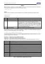
Status LED Indication
Idle, low signal strength Flashes red once every three seconds
Idle, adequate signal strength Flashes green once every three seconds
Connecting to network Flashes blue every half a second
Connected to network Flashes blue once every three seconds
Failed to connect Flashes red every half a second
Data packet sent or received Cycles once rapidly through all three colours
Table 5 – Status LED Indication Modes
5.1.2 Diagnostic LEDs
The iRIS has eight internal LED indicators that are useful for diagnostic purposes. Please note that these
indicators are only active in certain power management modes (see the features Section 2.8.4 for details on
power management). Also be aware that the functions of some of these LEDS are different on the earlier
V1.1 PCB version. See Appendix 13.4 for details.
NOTE: The diagnostic LEDs are only visible if the PCB (printed circuit board) is exposed. For the
iRIS 220, the electronic assembly must be removed from the case. For the iRIS 320, the front of the
case must be opened.
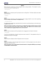
232 RX Flashes green when data is received from the RS232 port.
232 TX Flashes green when data is transmitted out the RS232 port.
Modem RX/TX Flashes green when there is receive or transmit activity with the wireless modem.
SDI-12 TX Flashes green when a SDI-12 message is transmitted.
DIGIN #1 Illuminated orange when Digital Input #1 is active (pulled down to 0V).
DIGIN #2 Illuminated orange when Digital Input #2 is active (pulled down to 0V).
DIGOUT #1 Illuminated orange when Digital Output #1 is active (delivering 12V).
DIGOUT #2 Illuminated orange when Digital Output #2 is active (pulled down to 0V).