


17
-
iRIS 220 / iRIS 320, V1.19 User Guide
3.4.6 Digital Outputs
The two digital outputs differ in their electrical configuration, although are identical in their logical operation.
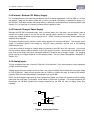
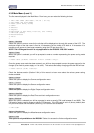
Digital Output 1 is open-drain pull-down and is capable of sinking up to 300mA at 30Vdc. An integral diode
provides transient protection. Typically this output could be used to drive a relay or lamp powered by an
auxiliary d.c supply (e.g. 12V). In this mode, the negative of the load supply must be connected to one of the
iRIS GND terminals.
WARNING: Although it may appear possible to directly control sensors by switching the sensor
negative supply lead using Output 1, this will introduce measurement errors and may possibly
damage the sensor. Always use Digital Output 2 to power sensors on a timed basis.
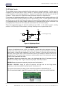
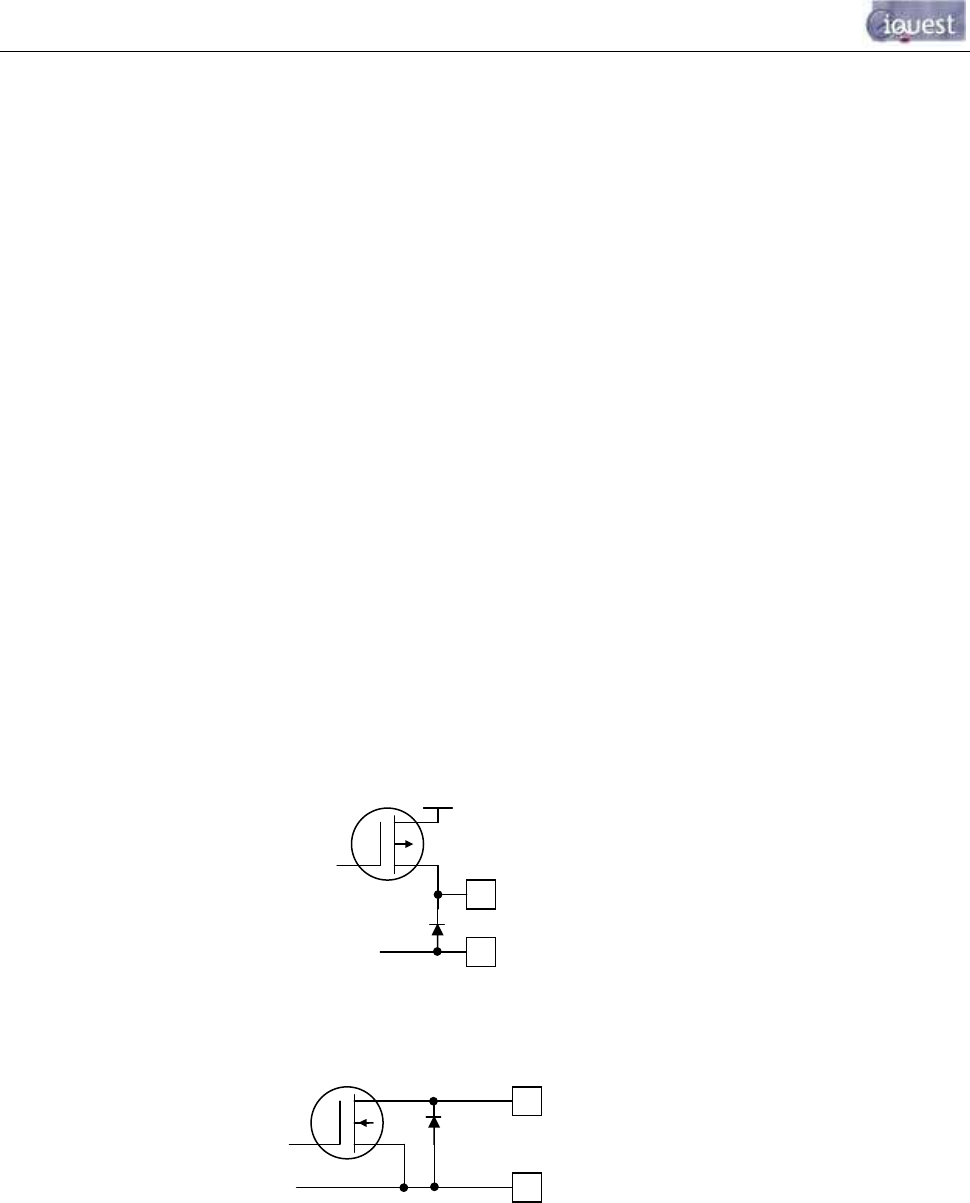
Digital Output 2 is a switched 12V output and is capable of sourcing up to 300mA. Typically this output will
be used to drive a sensor, relay or lamp powered by the iRIS 12V supply.
WARNING: Care should be taken to avoid the load discharging the internal and/or external 12V
battery. Ensure adequate power supply charging capacity is available to cater for the demands of
both the logger and load.
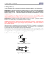
Digital outputs may be programmed to follow the state of the GPRS/CDMA-1X connection so that they will be
active when a GPRS/CDMA-1X session has been established. This mode can be used to control power to
an external data radio when using the iRIS 320 as a radio based gateway.
Alternatively, the outputs can also be programmed to follow a schedule for use in powering loads. Or they
can be selected for remote control directly from a HydroTel™ 2000 base station or operate in response to an
alarm trigger from Sensor #1 for applications such as triggering sediment samplers.
See Section 4.3.12 for details on the digital output modes.
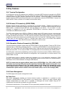
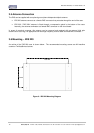
Figure 7 - Digital Output 1 Circuit
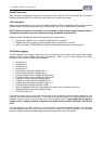
Figure 8 - Digital Output 2 Circuit
DOUT2
DGND
DOUT1
+12V
DGND