


iRIS 220 / iRIS 320, V1.19 User Guide - 32
32
iQuest (NZ) Ltd - PO Box 15169, Hamilton, New Zealand Tel: +64 7 857-0810 Fax: +64 7 857-0811 Email: iquest@iquest.co.nz
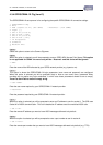
4.3.9 Sensor Cfg (Level 3)
The Sensor Cfg menu is used to configure each of the six main virtual sensors. Internal Sensors (7-9)
provide a smaller sub-set of these settings as most of the parameters are known and fixed. Refer to the
datalogging features (Section 2.8.5) of this manual for a discussion on datalogging and virtual sensors. This
menu option also shows the current scaled measurement value for the selected sensor.
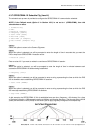
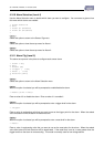
* Sensor 1 Cfg
(Now: 1.9620)
0 Exit
1 Source [1: Analog 1]
2 Name [Water Lvl]
3 Mode [Period Avg+Min+Max]
4 Multiplier [ 0.001]
5 Offset [ 0.0000]
6 Log Multiplier [1000]
7 Log Rate [15min]
8 Alarms
9 Data
>
Option 0
Select this option to return to the main Sensor Cfg menu.
Option 1
When this option is selected you will be prompted to enter a number representing the source from which the
virtual sensor should acquire its data. Use zero to disable the sensor. Valid data sources are shown in the
table below. Note that analog inputs 3 and 4 will give zero on iRIS units with V1.1 revision hardware.
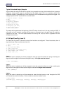
> Source (0.15)=
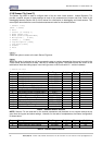
Source Description Raw Range Multiplier Offset Log Multiplier
0 Unused / disabled N/A N/A N/A N/A
1 Analog Input 1 0 to 5000
2 Analog Input 2 0 to 5000
3 Analog Input 3 0 to 5000
4 Analog Input 4 0 to 5000
5 Pulse Counter on Digital Input 1 0 to 1
6 Pulse Counter on Digital Input 2 0 to 1
7 Auto Pulse Counter on Digital Input 1 0 to 1
8 Auto Pulse Counter on Digital Input 2 0 to 1
9 Frequency Counter on Digital In 1 0 to 5000Hz
10 Frequency Counter on Digital In 2 0 to 5000Hz
11 Up/Down Counter on Digital Ins 1 & 2 -32768 to 32767
12 High-speed Serial Instrument -32768 to 32767
13 Database Location -32768 to 32767
14 Received Signal Strength 0 to 31 (or 99) 1 0 1
15 SDI-12
Table 2 - Standard Sensor Sources
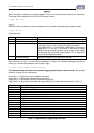
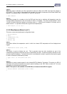
NOTE: Sensors 7-9 are reserved for the internal parameters and therefore do not require manual set-up
apart from the log rate and alarm settings. However, for the sake of completeness, the internal configuration
is shown below.
Sensor Description Raw Range Multiplier Offset Log Multiplier
7 Battery Voltage 0 to 1500 0.01 0 100
8 Supply (Charger) Input Voltage 0 to 3000 0.01 0 100
9 Internal Temperature -100 to 700 0.1 0 10
Table 3 - Internal Sensor Sources