iRIS 220 / iRIS 320, V1.19 User Guide - 60
60
iQuest (NZ) Ltd - PO Box 15169, Hamilton, New Zealand Tel: +64 7 857-0810 Fax: +64 7 857-0811 Email: iquest@iquest.co.nz
7 Analogue Input Scaling
This section explains the recommended procedure to use when scaling an analogue input (voltage or
current). It makes use of the scaling calculator provided in the iLink utility. However, the calculation can be
done manually using this formula. NOTE: mV = Input mV, EU = Engineering Units (scaled output e.g metres)
Multiplier = (Maximum EU – Minimum EU) / (Maximum mV – Minimum mV)
Offset = Maximum EU - (Multiplier * Maximum mV)
7.1 Example: A 4-20mA Water Level Sensor
In this example, we have a water level instrument connected to the iRIS Analogue Input 1. This instrument is
designed to provide a nominal 4-20mA signal for a 0-10 metre water level range. However, in the real world,
most instruments are not exact and a small difference in actual signal may occur. In addition, the current sink
resistor should ideally be 250Ω (giving 5V at 20mA), but only a 249Ω part was available. There is also the
small reduction in resistance caused by the internal input impedance of the iRIS input channel to take into
account (see Section 3.4.4 Analogue Inputs). Therefore the voltage measured by the iRIS for a given water
level is slightly different.
1. Power up the installation and allow to stabilize.
2. Set the instrument to zero water level (using a calibrator)
3. Note the actual voltage measured by the iRIS (view this on the LCD on “System Status 3”
screen. See Section 5.2.5. The LCD screen example below shows 993mV for a 0m input level.
4. Now increase the instrument input to full scale (10m) using the calibrator. Again, note the
measured voltage relating to this input level. This time it is 4961mV for a 10m level input.
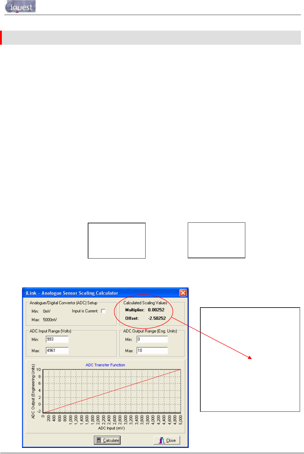
5. Using the iLink Scaling Calculator, enter the minimum and maximum measured voltages and the
levels they represent in the appropriate fields. Click the “Calculate” button to generate the
correct multiplier and offset parameters to use in the sensor setup menu for Sensor 1 as shown.
AI2: 0 mV
AI3: 0 mV
AI4: 0 mV
AI2: 0 mV
AI3: 0 mV
AI4: 0 mV
* Sensor 1 Cfg
(Now: 0.000)
0 Exit
1 Source [1: Analog 1]
2 Name [Water Lvl]
3 Mode [Period Avg]
4 Multiplier [ 0.00252]
5 Offset [ -2.50252]
6 Log Multiplier [1000]
7 Log Rate [15min]
8 Alarms
9 Data
>
Max mV
Max WL


