


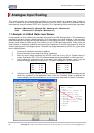
69
-
iRIS 220 / iRIS 320, V1.19 User Guide
13.5 Transistor Switch
On the older iRIS PCB, both digital outputs operate in an open-drain, pull-down mode. This configuration is
normally used to control an external relay or similar device and it offers the advantage of allowing a wide
range of relay supply voltages (up to 30V), which do not necessarily have to relate to the supply voltage of
the iRIS itself.
However, another common use for a digital output is to control a sensor such as a pressure transducer. In
this case, minimising power consumption is the main aim of the control. The optional transistor switching
module inverts the digital output and provides a switched power supply for the transducer or other device.
Being solid state, the extra current that a relay coil would draw is eliminated. On the later PCB (V1.2), digital
output 1 has the transistor switch incorporated on board and provides a switched 12V supply.
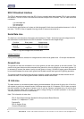
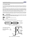
The switch module is a small unit that is able to fit inside the enclosure of an iRIS 320. It has three wires, two
of which are terminated with a bootlace ferrule for insertion into the iRIS I/O connector. The third (output)
wire has a screw terminal to attach the transducer supply wire. The wires and their functions are as follows:
RED: Supply Voltage In
For sensors requiring a 12V supply, connect this wire to the 12V+ terminal of the iRIS. For higher voltage
levels (up to 30V) connect this to the positive lead of a suitable dc power supply and also connect that power
supply’s negative lead to the GND terminal or GND terminal of the iRIS.
PURPLE: Switched Output
Connect the transducer (or other load) supply wire to this wire.
GREY: Control
Connect this wire to the appropriate digital output. Normally DO1.
The module has a small red LED that will be illuminated when the digital output is activated.
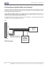
Figure 17 - Transistor Switch - Module Overview
Switching Module Specification
Maximum Supply Voltage: 30V
Maximum Switching Current: 300mA
Lead Length: 100mm
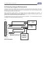
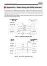
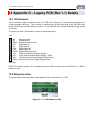
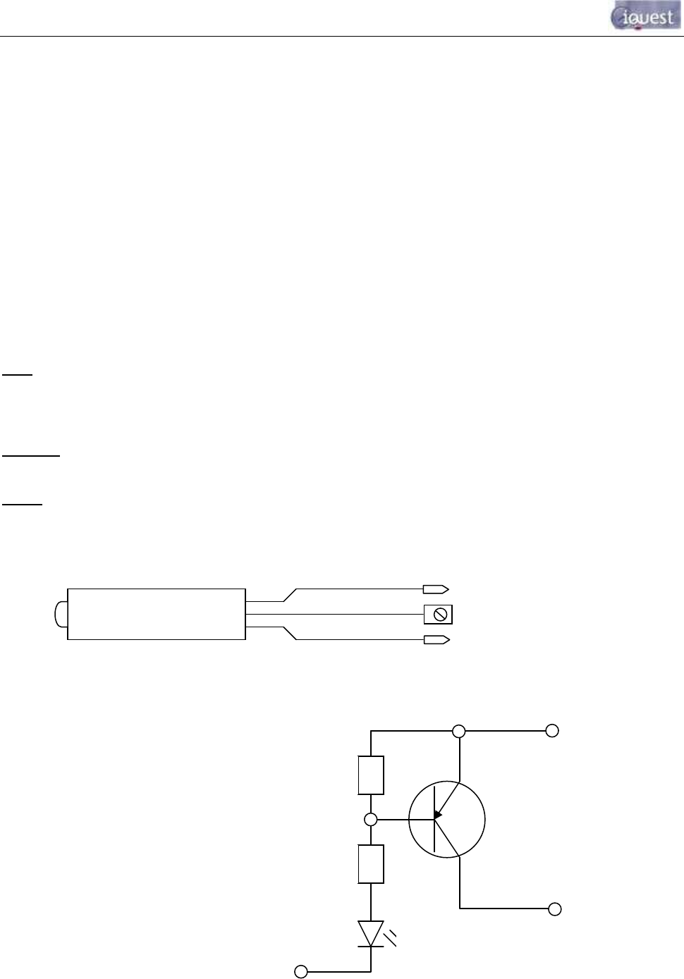
Figure 18 - Transistor Switch - Circuit Diagram
Purple (Output)
Red (Supply)
Grey (Control)
Switch Module
LED
Indicator
LED
Purple
(Output)
Grey
(Control)
2K2
4K7
E
C
B
Red
(Supply)
BC327 or
equivalent
PNP 45V
500mA