


37
-
iRIS 220 / iRIS 320, V1.19 User Guide
Option 2
When this option is selected you will be prompted to select the switching polarity of the output. This relates to
the output’s electrical state with respect to its logical on/off state.
If the polarity setting is 0 (normal), the output will actively pull down to 0V when the output logical state is on
and be high impedance (open-circuit) when the output is logically off.
If the polarity setting is 1 (inverted), the output will be high impedance (open-circuit) when the output logical
state is on and be actively pulled down to 0V when the output is logically off.
> Polarity (0:Normal 1:Inverted)=
Option 3
When this option is selected you will be prompted to enter a number representing the operating mode of the
output.
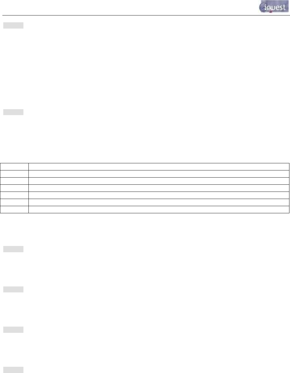
> Mode (0..5)=
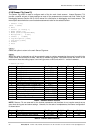
Valid modes are:
Source Description
0 Follow GPRS/CDMA/CSD Link State. I.e. Output is on if communication link is on-line.
1 Follow Schedule as defined by the settings in options 3-6.
2 Remote Control from Base. DO1 is controlled by bit 0 of d1000, DO2 by bit 1 of d1000.
3 Low Trigger. Activate when Sensor 1 last logged value <= trigger setpoint and trigger enabled.
4 High Trigger. Activate when Sensor 1 last logged value >= trigger setpoint and trigger enabled.
5 Force output permanently on. Required for both outputs if Unidata high-speed encoder used.
NOTE: If DO1 is set to mode 1 (Schedule) it will be forced on while a user is logged on via the
LCD/keypad interface. This is to power up a controlled sensor for calibration purposes.
Option 4
When this option is selected you will be prompted to enter the length of time in seconds that you want the
iRIS to keep the output energised if the mode is set to 1 (Schedule).
> Duration (sec)=
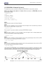
Option 5
When this option is selected you will be prompted to enter the length of time in minutes between the
successive operations of the output if the mode is set to 1 (Schedule).
> Frequency (min)=
Option 6
When this option is selected you will be prompted to enter a string representing the time at which the iRIS is
allowed to start controlling the output if the mode is set to 1 (Schedule).
> Start Time (HHNN)=
Option 7
When this option is selected you will be prompted to enter a string representing the time at which the iRIS
must stop controlling the output if the mode is set to 1 (Schedule).
> End Time (HHNN)=
NOTE: See Section 4.3.7, titled GPRS/CDMA-1X Schedule Cfg for details on how these parameters
configure the schedule operation.