


Powerware 9335 (80 kVA and 120 kVA) Installation and Operation 2-1
164201396 REV A 071103
2.1 Preliminary Installation Information
Refer to the following while installing the UPS system:
•
Refer to Appendix A of this manual for installation drawings and additional
installation notes.
• Dimensions in this manual, unless otherwise noted, are in millimeters and (inches).
•
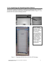
Do not tilt the cabinets more than
±
10 degrees during installation.
• The conduit landing plates are to be removed to add conduit landing holes as
required. Plate material is 14 gauge steel (2 mm. thick)
•
The cabinets must be installed on a level floor suitable for computer or electronic
equipment.
• If perforated floor tiles are required for ventilation, place them in front of the UPS.
Refer to Table J in Appendix A for equipment weight and point loading, and Figure
A–5 in Appendix A for air inlet locations.
•
Details about control wiring are provided in each procedure for connecting options
and features. Figure A–1 and Tables G and H in Appendix A identify the control
wiring terminations.
2
WARNING:
Only qualified personnel should perform installation. All wiring
and installation of the UPS system must be done in accordance
with the most current NEC standards or local electrical code.
I
nstalling the UPS System