


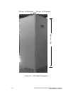
External
Battery
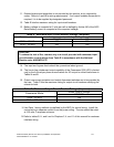
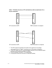
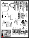
Powerware 9335 80 kVA and 120 kVA
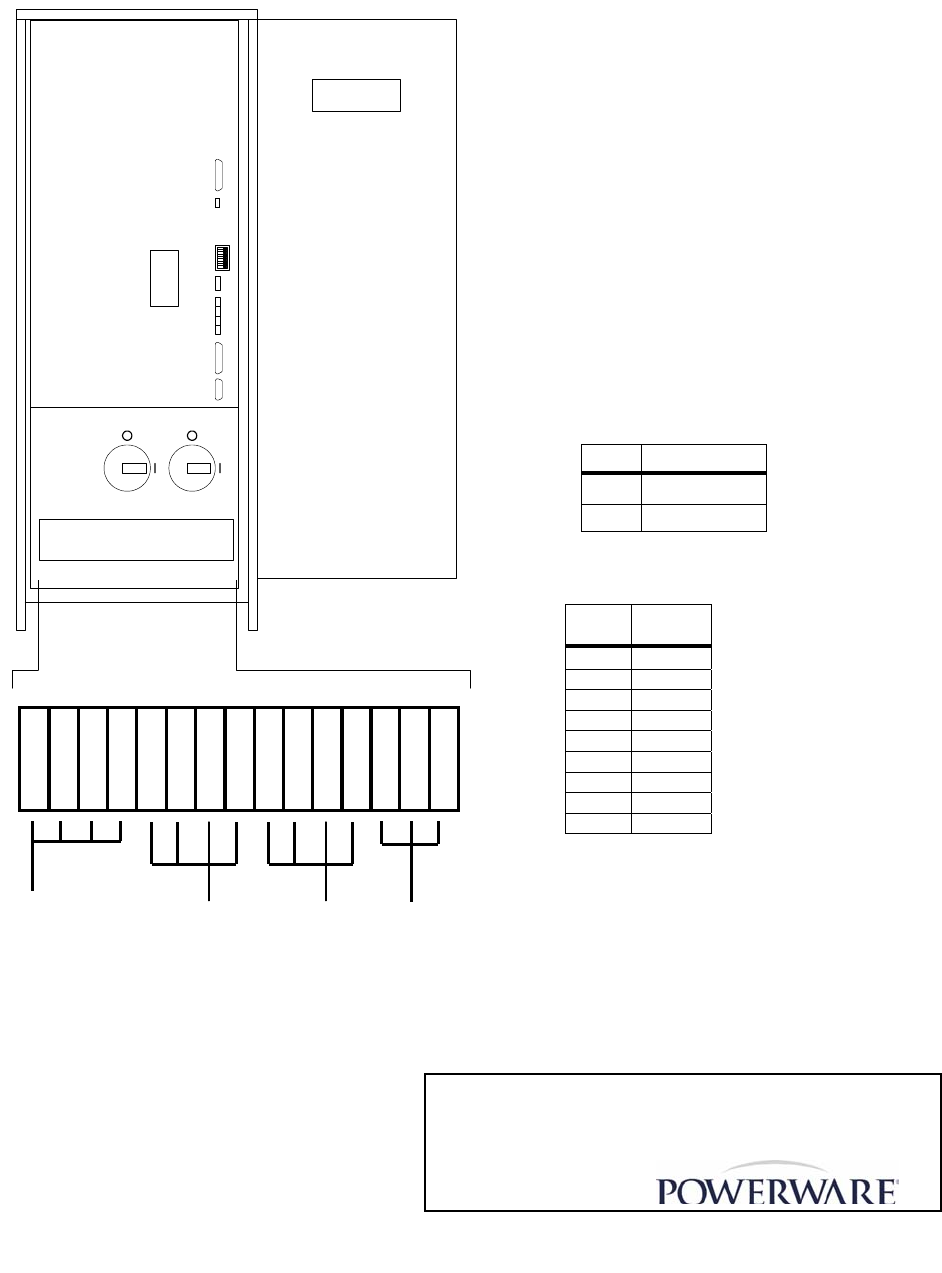
Front View showing customer connections
Control Panel
X2
X3
X4
X1
SW1-1
SW2-9
JD8
JD2
JD1
IA1 IA2
2N - N + 3N 1A 1B 3C 3B 3A 2C 2B 2A 1N 1C
Output
(To Load)
Utility Input
(Single
Feed)
Bypass Input
(Dual Feed)
On re
q
uest
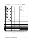
SW1-1 Module Type
HIGH Single Module
LOW Parallel Module
SW2-9 Single
Cabinet
1 ON
2 ON
3 ON
4 ON
5 ON
6 ON
7 ON
8 ON
9 ON
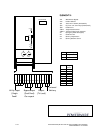
ELEMENTS:
IA1 Maintenance Bypass
IA2 Parallel Isolator
JD1 Smart Port- RS232 (SUB-D9P/F)
JD2 Dry Port-volt-free relays (SUB-D25/F)
JD8 Parallel Port
SW1-1 Single/Parallel Switch
SW2-9 System Configuration Switches
X1 Emergency Power OFF (EPO)
X2 Generator ON
X3 Battery Temperature
X4 Battery Breaker control
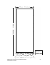
Figure A–1. Front View of 9335
A-10 Powerware 9335 (80 kVA and 120 kVA) Installation and Operation
164201396 REV A 07/11/2003