


5-10 Powerware 9335 (80 kVA and 120 kVA) Installation and Operation
164201396 REV A 071103
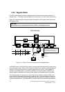
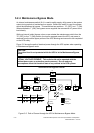
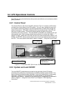
5.2.4 Maintenance Bypass Mode
An internal maintenance switch (IA1) is used to safely supply utility power to the system
output during periods of maintenance or repairs. Before this switch is used, the system
should be transferred to bypass. This switch has two positions: “O” (OFF) and “l” (ON).
When switched to “l” (ON), the bypass source supplies the commercial AC power to the
load directly.
While on internal (static) bypass, when a user rotates the maintenance switch from the
“O” (OFF) to the “l” (ON) position, the load is wrapped around the UPS, and power is
removed from the entire upper portion of the UPS allowing service work to be completed
on the UPS safely.
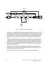
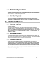
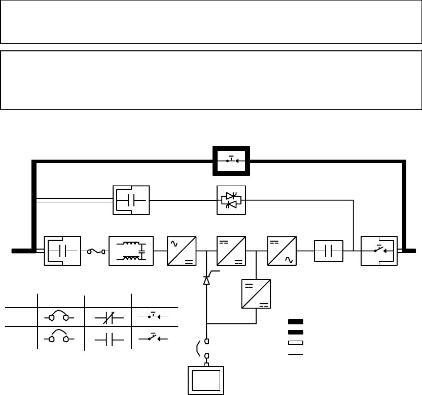
Figure 5–5 shows the path of electrical power through the UPS system when operating
in Maintenance Bypass mode.
Maintenance Bypass Mode
Battery
Charger
Rectifier
Input Filter
Booster
K4
K1
Inverter
K2
Battery
Breaker
Breaker Contactors
Closed
Open
Battery
IA2
IA1
Switches
Main Power
Trickle Current
Energized
De-Energized
F1
Figure 5–5. Path of Current through the UPS in Maintenance Bypass Mode
CAUTION:
The critical load is not protected while the UPS is in the Maintenance Bypass
mode.
DANGER:
LETHAL VOLTAGE PRESENT: This unit should not be operated with the
cabinet doors open or protective panels removed. Do not make any
assumptions about the electrical state of any cabinet in the UPS system.
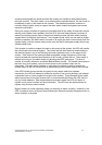
Static Switch