


1 2345678910
H
G
F
E
D
C
B
A
Checked by :
Replace :
Date:
Date:
Signature :
Signature :
Signature :
Modification
Modification
S06-0001ULA
Date:
Sheet :5 of : 5
H
G
F
E
D
C
B
A
1 2345678910
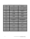
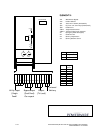
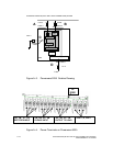
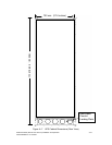
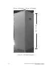
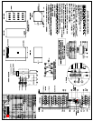
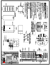
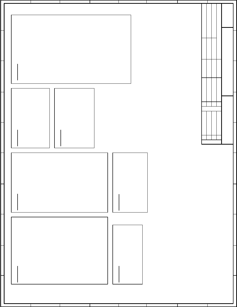
Electrical Diagram
Powerware 9335 80 and 120 kVA
NW4001
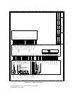
Functions:
y Electronic power supply
y Battery charger rating control
y Battery charger regulation
y Inverter rating control
y Inverter regulation
y Booster rating control
y Booster regulation
Connectors:
y J1 Booster and Battery control and regulation bus
y J2 Inverter control and regulation bus
y J3 Static Bypass thyristor control command
y J4 aux customer interface and parallel control signal bus
y J5 Display and customer interface bus
y J7 parallel control signal galvanic isolation
y C N 5 12 Vd c e l ectron i c su p pl y
y CN8 DC supply input
y CN9 Start up power supply 550Vdc
y CN10 Power supply for parallel data transmission
(safety)
y C N 1 1, 1 2 Cu st o m er a n d p a r a llel i n t erf ace sup p ly
(safety)
y CN16,17,18 Inverter voltage measurement
y CN39 Fan regulation
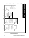
NW6002
Functions:
y Inverter IGB T dr iver c ircuit
y Booster IGBT driver circuit
y Battery IGBT c harger dr iver circuit
y Inverter current measurement
y Battery charger current measurement
Connectors:
y J1 Booster and Battery c ontrol and regulation bus
y J2 Inverter control and regulation bus
y CN1,3 battery charger IGBT driver signal
y CN2,4,5 Inverter current sensor input
y CN6,16 Booster shunt input
y CN9 Electronic supply
y CN10 Udc supply voltage output
y C N 1 2, 1 3 + Bo ost er I G B T d river sign al
y CN14,15 - Booster IGBT driver signal
y CN7,8,11 Temperature sensor input
y CN17..20 Inverter L1 IG BT driver signal
y CN22..25 Inverter L2 IG BT driver signal
y CN27..30 Inverter L3 IG BT driver signal
y CN21,26 Battery thyristor driver signal
NW6004
Functions:
y Static Bypass IGBT driver circuit
y Static Bypass current measurement
y Byp a s s a n d l o ad vo lt a g e m e as urem e nt
Connectors:
y J3 Static Bypass thyristor control command, static
bypass and load c urr ent and voltage
measurement
NW6009
Functions:
y Parallel transmission circuit, communication between UPSs
(safety)
y Aux. customer interface
y Free voltage contacts (safety)
y DC link charger circuit
y Po wer s u pply sta rtup re ctif i er
y User setup
y EPO input
y Contactor driver
Connectors:
y J4 aux customer interface signal bus
y J7 parallel interface bus
y CN6 Neutral i nput mains current (TA4)
y CN9 Start up power supply
y CN10 Parallel port power supply
y CN11 customer interface supply (safety)
y CN19 Mains input
y CN20 K2 dri ver output (output contactor)
y CN21 K1 driver output (power mains input contactor)
y CN22 K4 driver output (static bypass contactor)
y CN23 Output contactor (K2) status
y CN24 Maintenance bypass switch (IA1) status
y CN26 Output switch (IA2) status
y X1 Emergency off (normally closed)
y X2 Battery temperature input
y X3 Generator On input
y X4 Battery breaker control
y JD2 Voltage free contacts
y JD5 Parallel Port
NW4007
Functions:
y Customer interface
y Display
Connectors:
y J5 Display and customer interface bus
NW6029
Functions:
y Display interface board (galvanic insulation)
Connectors:
y J5 Display and customer interface bus input
y J51 Display and customer interface bus output
y CN12 Customer interface supply (safety)
NW6027
Functions:
y Conver ts Newave communication protocol to
Powerware XCP and Powerware XCP to
Newave communication protocol
y Manages multi-UPS communication in parallel
systems
Connectors:
y J9 Connects NW6027 to socket for XCP
format interface card, designed by
Powervare
y CN41 Connects NW6027 to NW6009
Drawn by :RMo
28/10/02
Figure A-6. System Information
A-14 Powerware 9335 (80 kVA and 120 kVA) Installation and Operation
164201396 REV A 07/11/2003