


5-6 Powerware 9335 (80 kVA and 120 kVA) Installation and Operation
164201396 REV A 071103
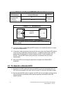
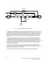
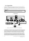
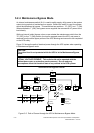
5.2.2 Bypass Mode
The UPS automatically switches to Bypass mode if it detects an overload, load fault, or
internal failure. The bypass source supplies the commercial AC power to the load directly.
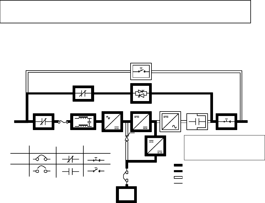
Figure 5–3 shows the path of electrical power through the UPS system when operating in
the Bypass mode.
Static Bypass
Battery
Charger
RectifierInput Filter Booster
K4
K1
Inverter
K2
Battery
Breaker
Breaker Contactors
Closed
Open
Battery
IA2
IA1
Switches
Main Power
Trickle Current
Energized
De-Energized
F1
Figure 5–3. Path of Current Through the UPS in Bypass Mode
In BYPASS mode, the output of the system is provided with three phase AC power directly
from the systems input. While in this mode, the output of the system is not protected from
voltage or frequency fluctuations or power outages from the source. Some power line
filtering and spike protection is provided to the load but no active power conditioning or
battery support is available to the output of the system in the bypass mode of operation.
The internal bypass is comprised of a solid state silicon controlled rectifier (SCR) static
switch (SSW), and a back feed protection contactor (K4). The static switch is rated as a
continuous duty device that is used anytime the boost converter and inverter is unable to
support the applied load. The static switch is wired in series with the back feed protection
CAUTION:
The critical load is not protected while the UPS is in the Bypass mode.
Static Switch
NOTE: In this mode K2 is energized.
Switching between bypass and inverter
is performed by either turning on or off
the inverter IGBT or bypass switch.