


11. External overcurrent protection is not provided by this product, but is required by
codes. Refer to A and B for wiring requirements. If an output lockable disconnect is
required, it is to be supplied by designated personnel.
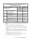
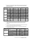
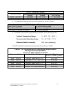
12. Table E lists the maximum rating for input circuit breakers.
13. Battery voltage is computed at 2 volts per cell as defined by Article 480 of the NEC.
Rated battery current is computed at the computed
voltage.
Table E. Maximum Input Circuit Breaker Ratings (Amperes)
Input Voltage Rating Powerware Model
480 VAC DC
9335 – 80 kVA 150 225
9335 – 120 kVA 225 300
CAUTION:
To reduce the risk of fire, connect only to a circuit provided with maximum input
circuit breaker current ratings from Table E in accordance with the National
Electric code, ANSI/NFPA 70.
14. The input and bypass feeds should be symmetrical about ground.
15. The line-to-line unbalanced output capability of the Powerware 9335 UPS is limited
only by the full load per phase current values for AC output to critical load shown in
Tables A and B.
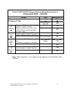
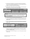
16. Output overcurrent protection and output disconnect switches are to be provided by
the user. Table F lists the maximum rating for output circuit breakers satisfying the
criteria for both.
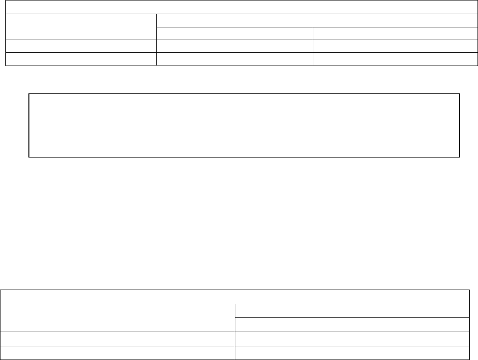
Table F. Maximum Output Circuit Breaker Ratings (Amperes)
Rated Output voltage
Powerware Model
480 VAC
9335 – 80 kVA 150
9335 – 120 kVA 225
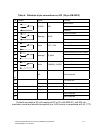
1. Use Class 1 wiring methods (as defined by the NEC) for control wiring. Install the
control wiring in separate conduit from the power wiring. The wire should be rated
at 150 volts, 5 amperes minimum.
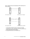
2. Refer to tables G, H, and I and to Chapters 2, 4, and 11 of this manual for customer
interface wiring.
Powerware 9335 (80 kVA and 120 kVA) Installation and Operation A-5
164201396 REV A 07/11/2003