


Powerware 9335 (80 kVA and120 kVA) Installation and Operation 8-3
164201396 REV. A 071103
12. Rotate the Maintenance Bypass Switch IA1 to the “O” (OFF) position. On the LCD
Display, “MANUAL BYP. OPEN” will appear followed by “LOAD NOT PROTECTED”.
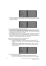
13. Using the Measurements menu (see sections 7.3.2 and 7.3.5) verify proper values
for output powers, voltages, currents and frequencies.
14. Perform Load transfer to Inverter
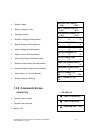
• Go to COMMANDS menu on UPS cabinet control panel and choose
command “LOAD TO INVERTER” to transfer the load to inverter output.
(see sections 7.3.2 and 7.3.6)
•
On LCD Display, “LOAD PROTECTED” will appear.
15. Repeat step 13 above to verify that all voltages, currents, power and frequency are
correct.
16. Once the above procedure is performed at initial start-up, subsequent start-ups may
be performed using only step 14, as long as other conditions are unchanged.
THE POWERWARE 9335 UPS NOW PROTECTS THE LOAD.
8.3 Complete Shutdown Procedure for the UPS
The Powerware 9335 may be shut down completely if the load does not need input
power for an extended period of time.
The UPS system may be switched to Maintenance Bypass Mode for service or
maintenance purposes, or transferred to the ECO-Mode if the load does not need the
highest degree of protection and efficiency is to be maximized.
The load may be disconnected by means of the two ON/OFF (LOAD-OFF) pushbuttons
for security or operational reasons.
1. Verify that the loads are shut down and that there is no need for power supply to the
load.
CAUTION:
Activation of both ON/OFF buttons simultaneously during normal operation
will switch off the UPS output and no longer supply power to the load.
CAUTION:
All the operations in this section must be performed by authorized service
technicians or by qualified internal personnel.
CAUTION:
If the Powerware 9335 will remain deactivated for an extended period of time,
provision must be made for periodic recharge of the system batteries.