


Powerware 9335 (80 kVA and120 kVA) Installation and Operation 10-3
164201396 REV. A 071103
power environment. If a power emergency occurs, the software initiates the saving of all
data and an orderly shutdown of the connected critical load.
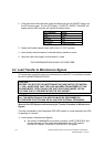
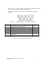
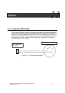
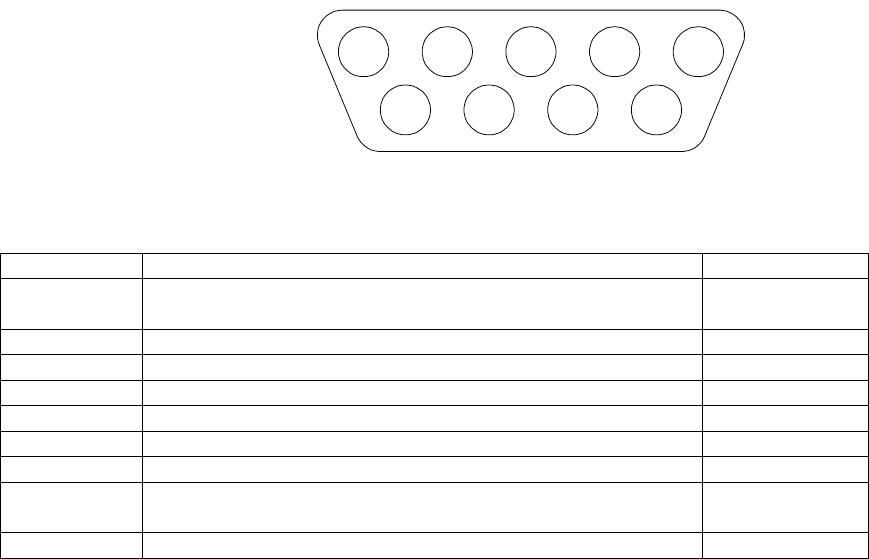
The cable pins are identified in Figure 10–2 and the pin functions are described in
Table 10–1.
Figure 10–2. The Communication Port on the Single Port Serial Card
Pin Number Function Input or Output
1 Low Battery Open Collector signal – pulls to common
when the UPS reaches low battery level
Output
2 RS-232 Transmit Data Output
3 RS-232 Receive Data Input
4 Plug and Play sense Input
5 Signal Common (tied to chassis) –
6 Tied internally to pin 4 Output
7 No Connection –
8 AC Fail Open Collector signal – pulls to common during
a power failure
Output
9 DC Supply Voltage (+8 to 24 volts DC power) Output
Table 10–1. Communication Port Pin Assignments
45 23
89
1
7 6