


8-4 Powerware 9335 (80 kVA and 120 kVA) Installation and Operation
164201396 REV A 071103
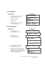
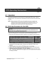
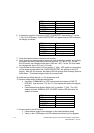
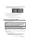
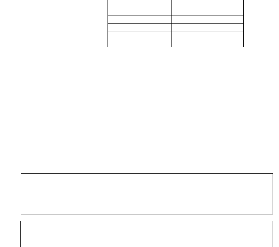
2. If the loads are all disconnected, press simultaneously the two ON/OFF buttons on
the UPS control panel. On the LCD Display, “LOAD OFF, SUPPLY FAILURE” will
appear and the LED-indicator will indicate as shown below:
LED Indicator Color
LINE 1 Green
LINE 2 OFF
BYPASS OFF
INVERTER OFF
BATTERY Flashing Green
3. Rotate the Parallel Isolator Switch (IA2) to the “O” (OFF) position.
4. Open battery cabinet breakers in external battery cabinets or racks.
5. Open the input utility supply circuit breakers, if used.
THE POWERWARE 9335 IS NOW VOLTAGE FREE.
8.4 Load Transfer to Maintenance Bypass
If it is necessary to perform service or maintenance on the UPS, it is possible to transfer
the UPS to MAINTENANCE BYPASS.
Status of the UPS-System before starting the Transfer Procedure to Maintenance
Bypass
The load is protected by the Powerware 9335 UPS system in normal operation (the UPS
is operating on inverter).
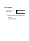
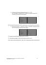
1) Load transfer to Maintenance Bypass
• Go to Menu COMMANDS and choose command “LOAD TO BYPASS” and
transfer the load to utility supply on control panel of the UPS cabinet.
On the LCD Display: “LOAD NOT PROTECTED” will appear.
CAUTION:
BEFORE YOU ROTATE THE MAINTENANCE BYPASS SWITCH TO POSITION
“I” (ON ), MAKE SURE THAT THE LOAD HAS BEEN TRANSFERRED TO THE
BYPASS MODE. EVEN THOUGH THE UNIT IS IN BYPASS MODE, LETHAL
V
OLTAGE IS STILL PRESENT WITHIN THE UPS CABINET.
CAUTION:
ALL THE OPERATIONS IN THIS SECTION MUST BE PERFORMED BY
AUTHORIZED ELECTRICIANS OR BY
Q
UALIFIED INTERNAL PERSONNEL.