


5-2 Powerware 9335 (80 kVA and 120 kVA) Installation and Operation
164201396 REV A 071103
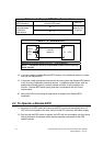
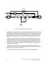
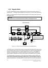
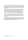
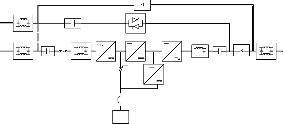
Battery
Charger
Rectifier
EMI Filter
EMI Filter
Input Filter
Booster
Contactor
K4
Contactor
K1
Inverter
N
Output
Contactor
K2
EMI Filter
Output filter
Output
Swi tch
IA2
Battery
Static Bypass
Swi tch
Mai ntenance
Bypass Switch
IA1
Fig. 5–1. Main Elements of the UPS System
If utility power is interrupted or falls outside the parameters specified in Chapter 13, “Product
Specifications,” the UPS uses a backup battery supply to maintain power to the critical load
for a specified period of time or until the utility power returns. For extended power outages,
the UPS is designed to operate with an alternative power system (such as a generator) or
will shut down your critical load in an orderly manner, if Powerware shutdown software is
used.
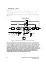
In the event of a severe output overload or failure of a critical internal UPS component, an
emergency bypass, consisting of a continuous duty static switch, and backfeed protection
contactor (K4) is utilized. The backfeed protection contactor is located in series with the
static switch, to ensure safety to anyone working upstream of the UPS system. For manual
transfers to bypass, the static switch is also used. The static switch is armed and ready
during both types of transfers.
If maintenance of the UPS system is required, an internal Maintenance Bypass switch
provides a means of isolating the UPS Rectifier/Booster/Inverter components for servicing,
while still supplying power to the critical load.
The operation of the UPS is described in greater detail in the following paragraphs.