


Powerware 9335 (80 kVA and120 kVA) Installation and Operation 7-1
164201396 REV. A 071103
7.1 Description
This chapter describes the UPS Control Panel, including controls and indicators, and
how to monitor UPS operation. The control panel is located on the front of the UPS
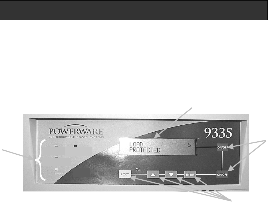
(see Figure 7–1).
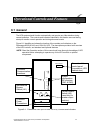
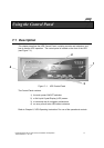
Figure 7–1. UPS Control Panel
The Control Panel contains:
1) the main power ON/OFF switches
2) a flat Liquid Crystal Display (LCD) screen
3) a horizontal row of navigation pushbuttons
4) an array of multi-color LED status indicators
Refer to Chapter 8, “UPS Operating Instructions” for use of the operational controls.
7
Usin
g
the Control Panel
A
LARM
LINE 2
BATTERY
BYPASS
LINE 1
INV
1
2
3
4