


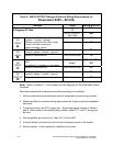
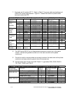
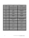
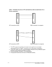
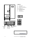

7. Terminals are UL rated at 90
o
C. Refer to Table C for power cable terminations and
Table D for conduit requirements. Figure A–1 shows the location of power cable
terminals inside the UPS.
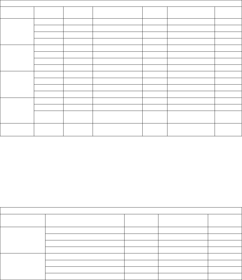
Table C. UPS Cabinet Power Cable Terminations for Powerware 9335 (80 kVA & 120 kVA)
Terminal
Function
Terminal Function Size of Pressure
Termination
Vendor Tightening Torque
N-M (lb-in.)
Int.Hex
Size (in.)
A Phase A 1 - #6-250 kcmils Cooper 42.4 (375) 3/8
B Phase B 1 - #6-250 kcmils Cooper 42.4 (375) 3/8
C Phase C 1 - #6-250 kcmils Cooper 42.4 (375) 3/8
AC Input to
UPS
Rectifier
N Neutral 1 - #6-250 kcmils Cooper 42.4 (375) 3/8
A Phase A 1 - #6-250 kcmils Cooper 42.4 (375) 3/8
B Phase B 1 - #6-250 kcmils Cooper 42.4 (375) 3/8
C Phase C 1 - #6-250 kcmils Cooper 42.4 (375) 3/8
AC Input to
Bypass
(Dual
Input)
N Neutral 1 - #6-250 kcmils Cooper 42.4 (375) 3/8
A Phase A 1 - #6-250 kcmils Cooper 42.4 (375) 3/8
B Phase B 1 - #6-250 kcmils Cooper 42.4 (375) 3/8
C Phase C 1 - #6-250 kcmils Cooper 42.4 (375) 3/8
AC Output
to Critical
Load
N Neutral 1 - #6-250 kcmils Cooper 42.4 (375) 3/8
+
Battery(+)
1 - #6-250 kcmils Cooper 42.4 (375) 3/8
N
Mid-point
1 - #6-250 kcmils Cooper 42.4 (375) 3/8
DC Input
from
Battery to
UPS
-
Battery (-) 1 - #6-250 kcmils Cooper 42.4 (375) 3/8
Customer
Ground
Protective
Ground
Protective
Ground
4 - #6-250 kcmils Cooper As Required
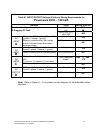
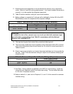
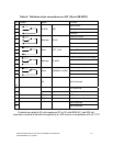
8. Per NEC article 300-20 (a), all three-phase conductors must be run in the same
conduit. Neutral and ground must be run in the same conduit as the phase
conductors.
9. Conduit is sized to accommodate one neutral conductor the same size as the phase
conductor and one protective ground wire of the same size.
10. Conduit sizes were chosen from NEC Table C1, type letters RHH, RHW, RHW-2,
TW, THW, THHW, and THW-2.
Table D. Power Cable Conduit Requirements Powerware 9335 (80 kVA & 120 kVA)
Powerware
Product Model
Terminal Wires in
Conduit
Minimum Conduit
Size (in.)
No. of
Conduits
Rectifier Input (A,B,C,N,G)
5 2.0 inches 1
Bypass Input (A,B,C,N,G)
5 2.0 inches 1
Ext. Battery Source (+,N,-,G)
4 2.5 inches 1
9335–80 kVA
Output (A,B,C,N,G)
5 2.0 inches 1
Rectifier Input (A,B,C,N,G)
5 2.5 inches 1
Bypass Input (A,B,C,N,G)
5 2.5 inches 1
Ext. Battery Source (+,N,-,G)
4 2.5 inches 1
9335–120 kVA
Output (A,B,C,N,G)
5 2.5 inches 1
A-4 Powerware 9335 (80 kVA and 120 kVA) Installation and Operation
164201396 REV A 07/11/2003