


8-2 Powerware 9335 (80 kVA and 120 kVA) Installation and Operation
164201396 REV A 071103
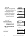
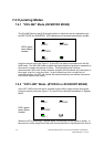
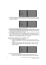
LED Indicator Color
LINE 1 Green
LINE 2 Green
BYPASS Green
INVERTER OFF
BATTERY Flashing Green
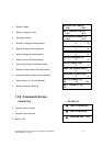
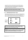
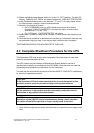
6. If necessary, perform Command: LOAD TO INVERTER (see sections 7.3.2 and
7.3.6) On LCD Display, “LOAD PROTECTED” will appear and the LED-indicators
will display as follows:
LED Indicator Color
LINE 1 Green
LINE 2 Green
BYPASS OFF
INVERTER Green
BATTERY Flashing Green
7.
Close the external battery cabinet circuit breaker.
8. Scroll through the measurements menu and verify that battery polarity and voltage
are proper and within prescribed limits (see sections 7.3.2 and 7.3.5). For the
80 kVA model, the voltages will be about +260 and –260. For the 120 kVA model,
the voltages will about +312 and –312 volts.
9. Close Parallel Isolator Switch (IA2) to position “I” (ON). UPS power is now present
on the output terminal block and “LOAD PROTECTED” will appear on the LCD
display. After 45-120 seconds, the battery LED will change from Flashing Green to
Solid Green. This state change will take up to one minute.
On initial start-up follow steps 9-14. On re-start stop at 9.
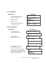
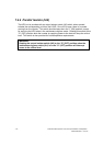
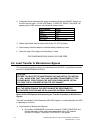
10. Perform load transfer to Maintenance Bypass
• Use Menu COMMANDS on UPS control panel and choose “LOAD TO
BYPASS” (see sections 7.3.2 and 7.3.6) to transfer the load to the bypass
source.
• Close Maintenance Bypass Switch (IA1) to position “I” (ON). The LCD
display will show “MANUAL BYP. CLOSED” and the LED indicators will
appear as follows:
LED Indicator Color
LINE 1 Green
LINE 2 Green
BYPASS Green
INVERTER Red
BATTERY Green
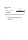
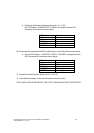
11. Connect load to the UPS output
• Close external output circuit breakers in the load distribution panel
•
Verify on the LCD Display and LED indicators that the load is on Bypass.