


Powerware 9335 (80 kVA and120 kVA) Installation and Operation 6-3
164201396 REV. A 071103
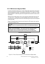
6.2.3 Maintenance Bypass Switch
An internal Maintenance Bypass Switch is provided to completely isolate the main power
processing of the UPS during service. The Maintenance Bypass Switch is described in
detail in Chapter 8, “UPS Operating Instructions.”
6.2.4 Cold Start Capability
The 9335 UPS system cannot be powered up without a utility input initially present.
Accordingly, it is not able to power a load if the system is not started first on utility power.
6.3 UPS Standard Features
6.3.1 Customer Interface
Computer Interface
One serial communications port
,
using the standard Powerware XCP interface, is
provided via a plug-in interface card inserted in the communications slot on the front of
the unit. This interface is supplied as standard with each Powerware 9335. You can use
this port to link the UPS to the features described in Chapter 10, “Communications” and
Chapter 11, “Options.”
6.3.2 Battery Management
A two-stage charging system ensures that the initial recharge is done in an optimal time,
with current limited, constant current, DC applied to the batteries. When terminal voltage
reaches a certain level, the charger switches to constant voltage.
6.3.3 Installation Features
Power wiring can be routed through the rear and bottom of the UPS cabinet with
connections made to easily accessible terminal blocks at the bottom front of the cabinet.
External monitoring and communication control wiring must be installed in accordance
with approved wiring methods. Communication wiring can be routed through the top of
each cabinet.
Communication option cards are quickly installed in the slot behind the front door panel.
X-slot cards are hot pluggable.