


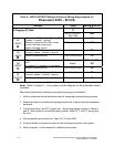
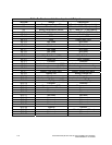

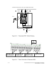
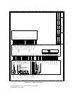

Table G. Customer Interface Inputs and Outputs
Terminal Name Description
X1 Emergency Power Off X1 – 1 and X1 – 2 (no polarity)
X2 Generator On X2 – 1 and X2 – 2 (no polarity)
X3 Battery temperature sensor X3 – 1 and X3 – 2 (no polarity)
X4 Battery Shunt trip breaker control X4 – 1 and X4 – 2 (+12V & com)
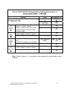
JD-1-1 Not Used Not Used
JD-1-2 TXD Input to UPS
JD-1-3 RXD Output from UPS
JD-1-4 Not Used Not Used
JD-1-5 Return Common
JD-1-6 Not Used Not Used
JD-1-7 Not Used Not Used
JD-1-8 Not Used Not Used
JD-1-9 Not Used Not Used
JD-2-1 Utility Fail Alarm (NO) Utility Fail Alarm
JD-2-2 Utility OK Utility Present
JD-2-3 Common Common
JD-2-4 Load on Inverter message (NO) Load on inverter message
JD-2-5 Load on inverter message (NC) Load not on inverter message
JD-2-6 Common Common
JD-2-7 Battery Low Alarm (NO) Battery voltage low alarm
JD-2-8 Battery OK Battery voltage OK
JD-2-9 Common Common
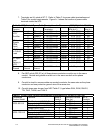
JD-2-10 Load on utility (bypass mode) Load on utility/bypass
JD-2-11 Load on utility/bypass (NC) Load not on utility/bypass
JD-2-12 Common Common
JD-2-13 Common Alarm (NO) Common alarm
JD-2-14 No alarm condition No alarm
JD-2-15 Common Common
JD-2-16 Not used Not used
JD-2-17 Not used Not used
JD-2-18 Not used Not used
JD-2-19 Not used Not used
JD-2-20 Not used Not used
JD-2-21 Not used Not used
JD-2-22 Ground Ground
JD-2-23 +12 volts +12 volts (I
max.
= 100 ma.)
JD-2-24 Not used Not used
JD-2-25 Not used Not used
A-6 Powerware 9335 (80 kVA and 120 kVA) Installation and Operation
164201396 REV A 07/11/2003