


7-2 Powerware 9335 (80 kVA and 120 kVA) Installation and Operation
164201396 REV A 071103
7.2 Using the Control Panel
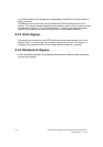
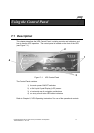
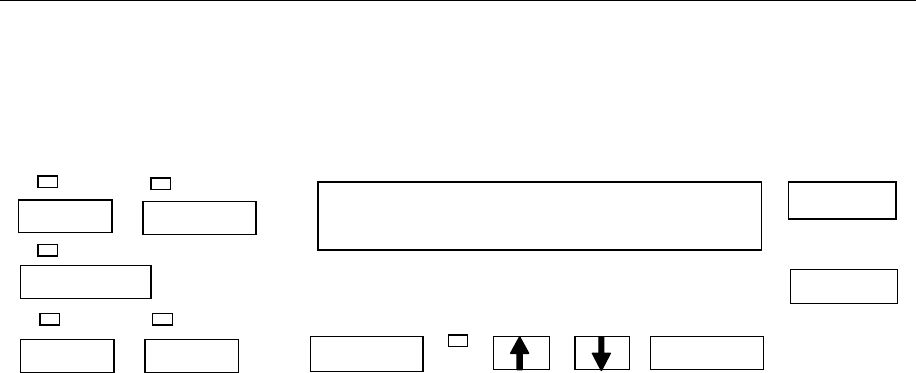
The Control Panel provides an operator interface with the UPS system. Figure 7–2
identifies the display and pushbutton areas discussed in the following sections as well as
LED indicators that provide a visual display of system operating status.
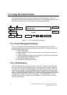
Figure 7–2. LCD Screen and Pushbuttons
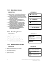
7.2.1 Power Management Display
The 2 x 20 character LCD Screen simplifies the communication with the UPS and
provides the necessary monitoring information about the UPS. The menu driven LCD
Screen enables access to the
1) EVENT REGISTER
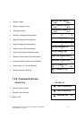
2) Measurements of input and output voltage, current, frequency, power and
battery runtime
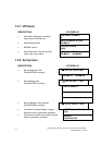
3) System commands for start-up and shut-down of the UPS and load transfer
from INVERTER to BYPASS and return
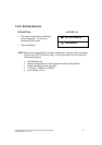
4) DIAGNOSIS (SERVICE MODE)
5) Adjustments and testing information
7.2.2 LED Indicators
The LED indicators display the general status of the UPS. Indicators show the power
flow status and in the event of power failure or load transfer from inverter to bypass or
vise-versa, the corresponding LED indicators will change color from green (normal) to
red (warning). The LINE 1 and LINE 2 LEDs indicate the availability of the input power
supply. The INVERTER and BYPASS LEDs, if green, indicate which of the two power
paths is supplying power to the critical load. When the battery is supplying the load, due
to supply failure, the BATTERY LED will be flashing. The ALARM LED is a visual
indication of any internal or external alarm conditions. At the same time, an audible
alarm will be activated.
LOAD S
PROTECTED
ON/OFF
ON/OFF
RESET
ENTER
A
LARM
LINE 2
LINE 1
BATTERY
BYPASS
INV