


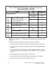
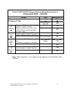
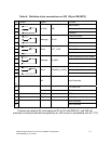

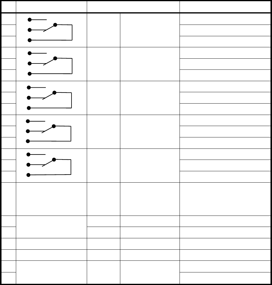
Table H. Definition of pin connections on JD2 (25 pin DB-25P/F)
Pin Contact Signal Function
1
Mains failure
2
ALARM MNS Mains present
3
Common
4
Load on inverter
5
Message LD-INV
6
Common
7
Battery low
8
Alarm BATT_LOW Battery OK
9
Common
10
Load on Mains (BYPASS mode)
11
Message LD_MNS
12
Common
13
Common Alarm
14
Alarm COMMON_ALARM No Alarm Condition
15
Common
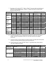
16
-
19
NC
Not Connected
20 For future use
21
For future use
22
PS_12 GND
23
PS_12 + 12V (Imax = 100 mA)
24
Not Connected
25
Not Connected
Contacts are rated at 60 volts maximum DC or 30 volts RMS AC, and 500 mA.
maximum current and should be supplied by a LVLE source in compliance with UL 1778
Powerware 9335 (80 kVA and 120 kVA) Installation and Operation A-7
164201396 REV A 07/11/2003