


H
G
F
E
D
C
B
A
Checked by :
Replace :
Date:
Date:
Signature :
Signature :
Signature :
Modification
Modification
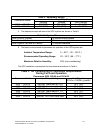
S06-0001ULA
Date:
Sheet : 1 of : 5
H
G
F
E
D
C
B
A
1
2345678910
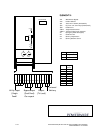
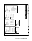
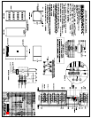
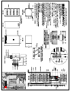
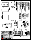
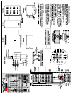
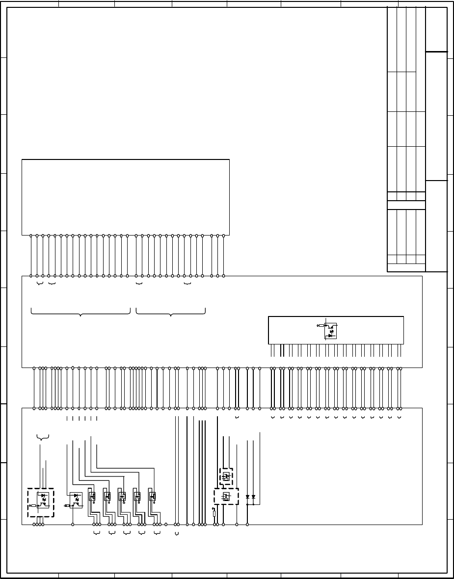
Electrical Diagram
Powerware 9335 80 and 120 kVA
Thy_Batt_Neg
1
2
4
U_Batt_Neg
5
U_Batt_Pos
Thy_Batt_Pos
7
8
9
I_Batt_Ch_Neg
10
Tar_Bch_Neg_L
11
Tar_Bch_Pos_H
12
Batt_Ch_Cntr
13
Tar_Bch_Neg_H
14
Sel_Batt
15
PS _B ch
16
+12V_Driver
17
+12V_Driver
20-12V_Driver
21
Tar_Bch_Pos_L
22
Temp_Res
23
Tem p _B oo st
Bst_On_Neg
26
27
28
I_Bst_Max_Neg
29I_ B s t _ Ma x_ Po s
30
I_Batt_Ch_Pos
34
U_Dc_Pos
Bst_On_Pos
31
32
35
I_Bst_Cntrl_K_
P
36
I_Bst_Cntrl_A_
P
38
I_Bst_Cntrl_K_
N
39
I_Bst_Cntrl_A_
N
40
U_Dc_Neg
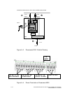
NW4001 Control Electronics
J3
1
2
4
5
7
8
9
10
11
12
13
14
15
16
17
20
21
22
23
26
27
28
29
30
34
31
32
35
36
38
39
40
NW6004 Bypass Control
J1
NW6009 Relay Control & Customer Interface
3
Common_Alarm
3
J4 J4
Ld_On_Inv
4
Batt_Low
5
Ld_On_Mains
6
2
Mains_OK
2
7
+5 V
7
9TXD- 232
9
10
RXD-232
10
11
Modem
11
1
Customer_In
12
18
PS+24
18
Battery charger
and battery
thyristor control
signals
Booster
control
signals
19
PS+24
19
25
25
Par_sys tem _In
26
26
Par_system_Out
27
27
B_Ch_cntrl
28
28
K_Byp_Pos
29
29
K_B yp _Ne g
37
37
T1 _P ar_L 1
39
39
T2 _P ar_L 1
41
41
T1 _P ar_L 2
43
43
T2 _P ar_L 2
45
45
T1 _P ar_L 3
47
47
T2 _P ar_L 3
53
53
TDX_Par
60
60
Inv_Fail
13
13
Off_Out
I_N
31
32
31
32
30
30
K_Inv_Status
24
24
K_By p_S tatu s
22
22
K_Ba tt
23
23
K1
55
55
Reset_Cntrl
56
56
57
57
58
58
Serial Port
and XCP
3
4
5
6
2
12
JD2
+12VE
15
14
13
+12VE
6
5
4
+12VE
9
8
7
+12VE
12
11
10
+12VE
20
JD1
TXD232
2
1
3
RXD232
4
DT R
23
1
CN23
1
CN34
1
CN6
2
33
58
Gen_On
2
X2
1
3
U_RCT_L1
12
U_RCT_L2
14
U_RCT_L3
CN19
1
CN23
K_sof t_St art
13
13
1
CN20
K3
Load_OFF
21
21
K_Batt_err
20
20
K_I nv
62
+12VE
62
28
28
Thy_Batt_Pos
29
29
Bypass_cntrl
1
CN22
35
35
Ld_Cntrl_Unit
1
1
Ld_Cntrl_Bus
2
2
J7 J7
3
3
Byp_Serv_Cntrl
4
4
5
5
Q2_Status
6
6
8
8
Byp_Serv_Cntrl
7
7
10
10
RXD _Pa r
9
9
11
11
M_S_Bus
12
12
14
14
T1_ B us_P ar_L 1
13
13
16
16
T2_ B us_P ar_L 1
15
15
18
18
T1_ B us_P ar_L 2
17
17
20
20
T2_ B us_P ar_L 2
19
19
22
22
T1_ B us_P ar_L 3
21
21
24
24
T2_ B us_P ar_L 3
23
23
26
26
Connector_Error
25
25
27
27
I n v_ F a il _Bus
28
28
29
29
Frq_Temp_Batt
30
30
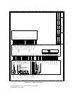
Drawn by :RMo
+12VC
Ld_On_Mains
Batt_Low
Ld_On_Inv
Common_Alarm
Mains_OK
C us t om e r_I n
+5VC
1
2345678910
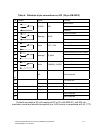
Figure A-5. System Information
Powerware 9335 (80 kVA and 120 kVA) Installation and Operation A-13
164201396 REV A 07/11/2003