


Powerware 9335 (80 kVA and 120 kVA) Installation and Operation A-1
164201396 REV A 07/11/2003
A
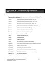
The information in this appendix will help you plan for and install your UPS system. This
appendix contains the following:
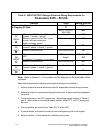
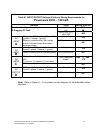
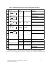
Table A Input/Output Ratings and external wiring 9335 – 80
Table B Input/Output Ratings and external wiring 9335 – 120
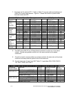
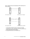
Table C UPS Power Cable Terminations 9335 – 80 & –120
Table D Power Cable Conduit Requirements 9335 – 80 & –120
Table E Maximum Input Circuit Breaker Ratings
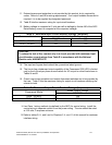
Table F Maximum Output Circuit Breaker Ratings
Table G Customer Interface Inputs and Outputs
Table H Customer interface to JD2
Table I Customer connections to JD1
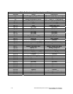
Table J Equipment Weight
Table K System Clearances
Table L Air Conditioning or Ventilation Requirements
Figure A–1 Front View of Powerware 9335 showing customer connections
Figure A–2 Label of Powerware 9335
Figure A–3 One-line diagram of Powerware 9335
Figure A–4 Power terminal connections for Powerware 9335
Figure A–5, –6 UPS System Information
Figure A–7, –8 UPS Cabinet Dimensions
A
ppendix A – Customer Information