


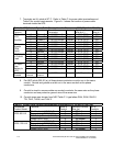
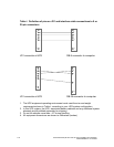

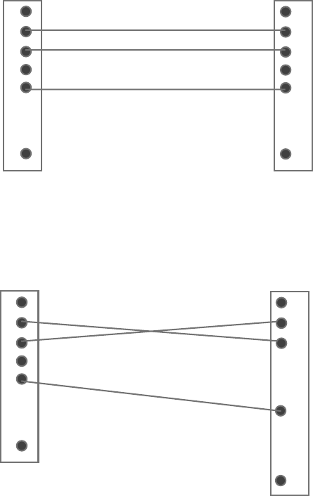
Table I. Definition of pins on JD1 and interface cable connections to 9 or
25 pin connectors.
5
.
.
.
9
3
2
1
5
9
.
.
.
1
2
3
JD1 connector at UPS DB-9 connector to computer
.
.
.
.
7
.
.
.
25
3
2
1
5
9
.
.
.
1
2
3
JD1 connector at UPS DB-25 connector to computer
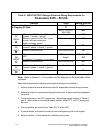
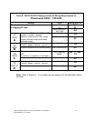
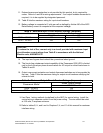
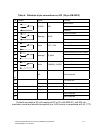
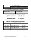
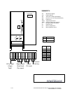
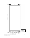
1. The UPS equipment operating environment must meet the size and weight
requirements shown in Table J, according to your UPS system configuration.
2. In this UPS system, the UPS, associated battery cabinets and any additional system
elements are all palleted separately for shipping.
3. Do not tilt cabinets more than ±10˚ during handling.
4. All equipment dimensions are shown in millimeters (inches).
A-8 Powerware 9335 (80 kVA and 120 kVA) Installation and Operation
164201396 REV A 07/11/2003