


Powerware 9335 (80 kVA and 120 kVA) Installation and Operation vi
164201396 REV. A 071103
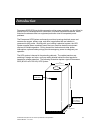
Figure 1 – 1 Powerware 9335 (80 kVA and 120 kVA) UPS Cabinet
Figure 4 – 1 Typical Remote EPO Control
Figure 5 – 1 Main Elements of the UPS System
Figure 5 – 2 Path of Current through the UPS in Normal Mode
Figure 5 – 3 Path of Current through the UPS in Bypass Mode
Figure 5 – 4 Path of Current through the UPS in Battery Mode
Figure 5 – 5 Path of Current through the UPS in Maintenance Bypass Mode
Figure 6 – 1 Powerware 9335 (80 kVA and 120 kVA) Controls and Indicators
Figure 6 – 2 Powerware 9335 (80 kVA and 120 kVA) Control Panel
Figure 7 – 1 UPS Control Panel
Figure 7 – 2 LCD Screen and Pushbuttons
Figure 7 – 3 LCD Screen Navigation Chart
Figure 10 – 1 X – Slot Location on Front of Powerware 9335 UPS Cabinet
Figure 10 – 2 The Communication Port on the Single Port Serial Card
Figure 11 – 1 Generator ON Connection
L
ist of Figures