CDM-600 Satellite Modem Revision 7
Preface MN/CDM600.IOM
iv
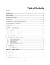
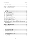
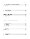
2.5 Connect External Cables............................................................................................................2–4
CHAPTER 3. FUNCTIONAL DESCRIPTION........................................................................3–1
CHAPTER 4. PHYSICAL DESCRIPTION.............................................................................4–1
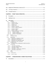
4.1 Introduction.................................................................................................................................4–1
4.2 Front Panel ..................................................................................................................................4–1
4.3 Rear Panel....................................................................................................................................4–2
4.3.1 IEC Line Input Connector.....................................................................................................4–2
4.3.2 Rx and Tx IF Connectors (J1 and J2) ...................................................................................4–3
4.3.3 Overhead Data Connector (P3A) ..........................................................................................4–3
4.3.4 Data Interface Connector (P3B)............................................................................................4–3
4.3.5 External Reference Connector (J9).......................................................................................4–3
4.3.6 Audio Connector (P4A) ........................................................................................................4–3
4.3.7 Remote Control connector (P4B)..........................................................................................4–4
4.3.8 IDR Alarm connector (P5A).................................................................................................4–4
4.3.9 Form C Traffic Alarm Connector (P5B)..............................................................................4–4
4.3.10 Auxiliary Serial Connector (P6) ...........................................................................................4–4
4.3.11 Balanced G.703 Interface Connector (P7) ............................................................................4–4
4.3.12 IDI, DDO Connectors (J10A and J11A)...............................................................................4–5
4.3.13 Unbalanced G.703 Tx/Rx (J10B and J11B).........................................................................4–5
4.3.14 External Frequency Reference Connector (J12) This is an SMA female connector. It is an
optional connector used to permit the connection of a high-stability external reference signal..........4–5
4.4 Dimensional Envelope ................................................................................................................4–6
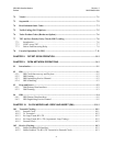
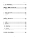
CHAPTER 5. CONNECTOR PINOUTS................................................................................5–1
5.1 Connector Overview ...................................................................................................................5–1
5.2 BNC Connectors..........................................................................................................................5–2
5.3 Overhead Interface Connector (P3A) .......................................................................................5–2
5.4 Data Interface Connector (P3B) ................................................................................................5–3
5.5 Audio Interface Connector (P4A)..............................................................................................5–4
5.6 Remote Control Interface Connector (P4B).............................................................................5–4
5.7 IDR Backward Alarms Connector (P5A) .................................................................................5–5
5.8 Unit Alarms (P5B).......................................................................................................................5–5
5.9 Auxiliary Serial Connector (P6) ................................................................................................5–6


