CDM-600 Satellite Modem Revision 7
Physical Description MN/CDM600.IOM
4–4
4.3.7 Remote Control connector (P4B)
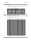
The Remote Control connector is a 9-pin ‘D’ type male (DB-9-M). Access is provide to
remote control ports of the modem, both EIA-232 and EIA-485.
4.3.8 IDR Alarm connector (P5A)
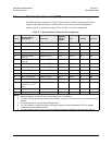
The Alarms connector is a 15-pin 'D' type female (DB15-F). Four Form C backward
alarm outputs specified by INTELSAT are found on this connector.
4.3.9 Form C Traffic Alarm Connector (P5B)
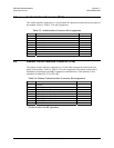
The Alarms connector is a 15-pin 'D' type male (DB15-M). This provides the user with
access to the Form-C relay contacts, which indicate the fault status of the unit. These are
typically connected to an external fault monitoring system, often found in satellite earth
stations. In addition, the receive I and Q demodulator samples are provided on this
connector. Connecting these signals to an oscilloscope in X, Y mode will provide the
receive signal constellation diagram, which is a useful diagnostic aid. A pin is also
provided which can mute the transmit carrier. This requires that the pin be shorted to
ground, or a TTL ‘low’, or an RS232 ‘high’ signal be applied. As an aid to antenna
pointing, or for driving step-track equipment, an analog AGC signal is provided on Pin 2
of this connector.
4.3.10 Auxiliary Serial Connector (P6)
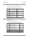
This is an additional EIA-232 serial port, which is only used when the modem is part of a
1:1 pair. It uses a USB Type B connector.
WARNING
Although this port uses a USB connector, the signals are not
USB compatible. Do NOT connect this port to the USB port of
a PC, or other computing device.
4.3.11 Balanced G.703 Interface Connector (P7)
A 15-pin 'D' type female (DB15-F) for balanced operation at the G.703 data rates of T1
(1.544 Mbps), E1 (2.048 Mbps) or T2 (6.312 Mbps).


