


2-6 0DJHOODQ 6FDQQHU
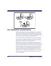
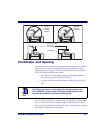
Counter Preparation. Since the majority of grocery checkout lanes are
designed as “left-hand take away,” the counter drawings in this section
focus on this counter design. Simply reverse the layout for a “right-hand
take away” requirement. The unit scans equally well in either of these two
configurations.
Liquid Drainage. Should a liquid spill occur, ensure that moisture can
flow through the checkstand without pooling.
Leveling. Plan ahead and provide screws/bolts in the checkstand mounts
and a leveling guide (board) to allow leveling of the scanner or scanning-
scale within the counter. Use a 0.375” thick board to replicate the mount-
ing flange on the long scanner or scanning-scale, and adjust screws or bolts
until the board is flush within the counter. Use a 4.0” wide board stood on
its end to adjust leveling screws/bolts in rail support applications.
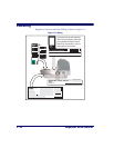
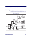
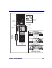
Cable Routing. Placement of the scanning-scale should be planned to
allow easy access to other components as well as optimize communication
between the scanner, the POS terminal and the optional Remote Scale
Display. Note that cables may drop straight down from the scanner’s con-
nector panel, or may be conveniently routed along the unit’s side using the
hardware provided. Do not route interface cables near any electrical
motors or other sources of electromagnetic interference.
Remote Scale Display Placement. The customer, and checker in some
instances, must be able to easily view and read the Remote Scale Display.
Ambient light and mounting height considerations are discussed later in
this section.
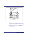
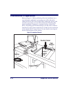
Vertical Clearance. Provision must be made to allow adequate space
above the scanner bonnet for removal and replacement of the All
Weighs™ Platter (the L-shaped platter). Optimal clearance permits the
platter to be grasped at its top vertical edge and lifted for removal without
obstruction (such as a fixed keyboard mount or any type of enclosure).
Should such an enclosure be unavoidable, an alternate method of platter
removal using two coins may be employed, however a minimum vertical
clearance of 1.5” (3.8 cm) MUST be provided (reference Figure 2-2).
Another consideration is that the scan zone must be kept free of obstruc-
tions such as enclosures, keyboard mounts, etc.