


17
2. Hardware Implementation of the LUFP7 Gateway
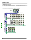
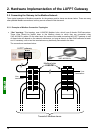
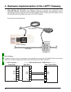
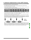
• “Bus” topology with VW3 A8 306 TF3 drop boxes: This topology uses VW3 A8 306 TF3 drop boxes to
connect each of the Modbus slaves to the main section of the Modbus network. Each box should be placed in
the immediate vicinity of the Modbus slave it is associated with. The cable for the main section of the Modbus
network must have male RJ45 connectors (like the VW3 A8 306 R•• cable used for the “star” topology). The
lead between the drop box and the slave or the Modbus gateway is an integral part of this box. The
connections are shown below:
Modbus
LUFP7 Gateway
Towards 2 Modbus slaves
VW3 A8 306 TF3
Line
termination
Towards 3 Modbus slaves
Towards 3 Modbus slaves
Line
termination