100
11. Appendix D: Sample Use under PL7 PRO
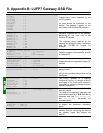
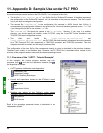
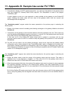
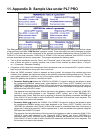
• Comprehensive display of LUFP7 gateway diagnostics, via a thorough interpretation of the gateway status
word (see chapter 5.2.2 Gateway Status Word, page 40). This interpretation is made in the program
“Handshake_lufp7”.
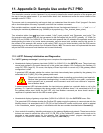
A button appears as soon as a new diagnostic is made available by the gateway for the Profibus-DP
master. Pressing that button takes the new value of the gateway status word into account and
acknowledges the new diagnostic.
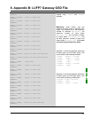
The
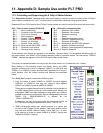
“Handshake_master” program assists the screen presented on the previous page in conducting the
following tasks:
• Display of two buttons meant for enabling and disabling exchanges on the gateway Modbus sub-network
See note (1).
•
Transmission (to the gateway) of the command related to the button pressed by the user. This is done only
once the gateway acknowledges the previous command, i.e. once bit 14 of the gateway status word has the
same value as bit 14 of the Profibus-DP master control word. (1)
In that case, bit 13 of the Profibus-DP master control word is updated in accordance with the user
command, and the value of its bit 14 is inverted to notify the gateway of the presence of a new command.
See note (1).
(1)
The LED, the two buttons, and the related processings, should not be used with the gateway default
configuration as the choice retained for the “Control/Status Byte” option is “Enabled but no startup lock”
(see chapter 5 Gateway Initialization and Diagnostics, page 37 and chapter 5.3 Diagnostic Only, page 41).
These elements are therefore only meant to make this example compatible with the “Enabled” option (see
chapter 5.2 Full Management, page 37).
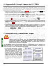
The
“Handshake_lufp7” program also assists the screen described on the previous page in conducting the
following tasks:
• Display the button meant to take the content of the gateway status word into account. This button is
displayed only if a new diagnostic is available, i.e. if the value of bit 15 of the gateway status word is
different from that of bit 15 of the Profibus-DP master control word.
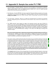
• When the user presses that button, the content of the gateway status word is analyzed in order to generate
four separate messages according to the following data: gateway input data update/validity (bit 13),
periodicity of Modbus exchanges (bit 12), error code (bits 8-11) and unit/nature of the data element related
to the error code (bits 0-7).
Bit 15 of the Profibus-DP master control word is then set to the same value as bit 15 of the gateway status
word to notify the gateway that the diagnostic has been taken into account and it can therefore deliver a
new one.


