23
2. Hardware Implementation of the LUFP7 Gateway
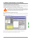
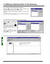
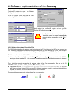
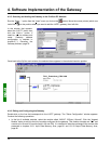
2.7. Configuring the Profibus-DP Communication Features
This configuration should be carried out when the gateway is powered off.
This task is limited to configuring the gateway's Profibus address, as the communication speed on the Profibus
network (9.6 kbits/s to 12 Mbits/s) is automatically detected by the gateway.
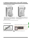
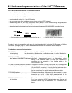
The two coding wheels used for configuring the gateway’s address are hidden behind the gateway cover
g
(see
illustration in chapter 2.2 Introduction to the LUFP7 Gateway, page 13). To remove this cover, all you have to do
is insert the end of a small flat screwdriver between the top of the hood and the gateway box, and then to pull it
out delicately.
The power supply of the gateway must be turned off before opening the cover.
Once the cover has been removed, make sure that you touch neither the electrical circuits nor
the electronic components.
2.7.1. Encoding the Gateway Address
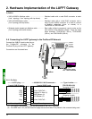
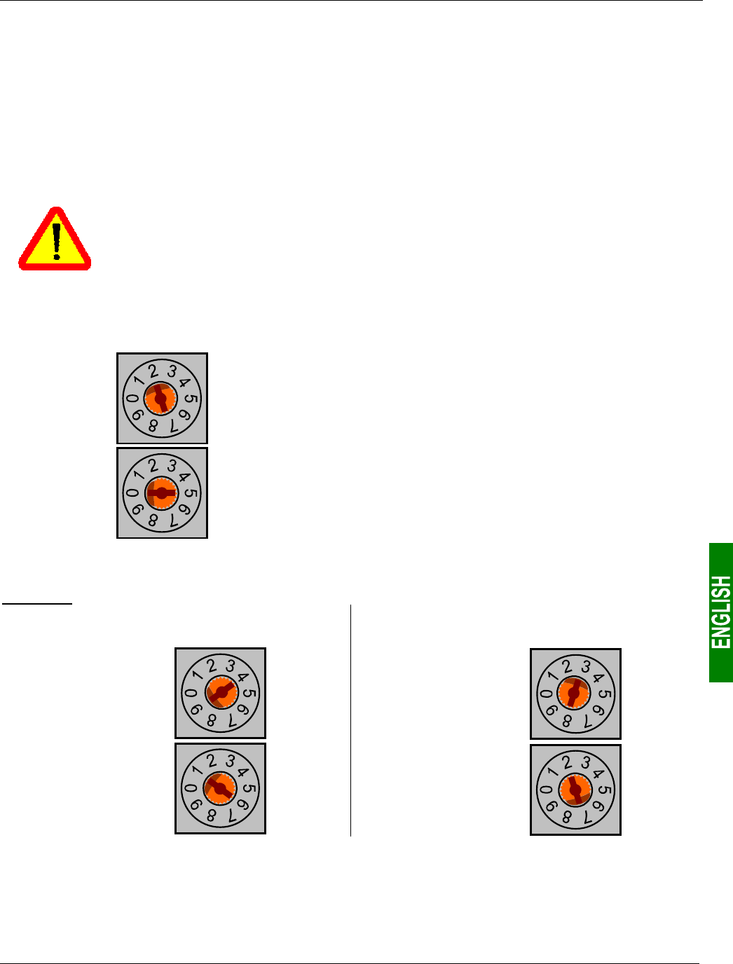
The LUFP7 gateway is identified on the Profibus-DP bus by its address, ranging from 1 to 99.
Tens
Units
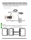
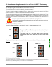
The gateway's Profibus-DP address depends on the position of the two
coding wheels represented on the left, in their factory-setting positions
(default address = 2).
This address is the sum of the decimal values given by the angular
positions of the bottom coding wheel (tens) and the top coding wheel
(units).
Any change to the gateway's address shall be taken into account only once it is powered on again.
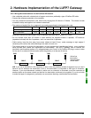
Examples:
Address = 19 Address = 73
Tens
Units
Tens
Units
2.7.2. No Internal Line Termination
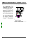
The LUFP7 gateway has no active line termination. You must therefore use a Profibus-DP connector with such a
termination if you place the gateway at one of the ends of a bus segment.


