19
2. Hardware Implementation of the LUFP7 Gateway
2.5.3. Wiring Recommendations for the Modbus Network
• Use a shielded cable with 2 pairs of twisted conductors,
• connect the reference potentials to one another,
• maximum length of line: 1,000 metres
• maximum length of drop line / tap-off: 20 metres
• do not connect more than 9 stations to a bus (slaves and one LUFP7 gateway),
• cable routing: keep the bus away from power cables (at least 30 cm), make crossings at right angles if
necessary, and connect the cable shielding to the earth on each unit,
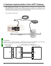
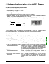
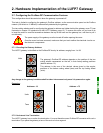
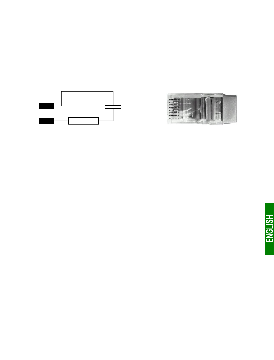
• adapt the line at both ends using a line terminator (see diagram and VW3 A8 306 RC termination below).
D(B)
D(A)
120 Ω
1 nF
4
5
— Line termination recommended at both ends of the line — — VW3 A8 306 RC line termination —
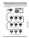
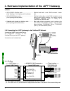
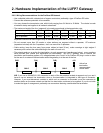
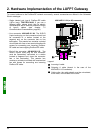
To make it easier to connect the units using the topologies described in chapter 2.5.1 Examples of Modbus
Connection Topologies, page 15, various accessories are available in the Schneider Electric catalogue:
1) Hubs, drops, taps, and line terminations:
LU9GC03 hub .....................
(“star” topology)
This passive box has 8 female RJ45 connectors. Each of these connectors can
be connected to a Modbus slave, to a Modbus master, to another Modbus hub,
or to a line termination.
VW3 A8 306 TF3 drop box......................
(“bus” topology with VW3 A8 306 TF3 drop boxes)
This passive box includes a short lead with a male RJ45 connecto
r
allowing it to be connected directly to a Modbus slave, without
having to use a different cable. It is fitted with 2 female RJ45
connectors for the connection of two Modbus cables of the
VW3 A8 306 R•• type.
2-way TSXSCA62 subscriber connector.
(“bus” topology with tap boxes)
This passive box has a printed circuit fitted with screw terminals
and allows the connection of 2 subscribers to the bus (2 female
15 point SUB-D connectors). It includes the line termination when
the connector is located at the end. It is fitted with 2 screw terminals
for the connection of two double twisted pair Modbus cables.
TSXCA50 tap box....................................
(“bus” topology with tap boxes)
This passive box allows a Modbus unit to be connected to a screw
terminal. It includes the line termination when the connector is
located at the end. It is fitted with 2 screw terminals for the
connection of two double twisted pair Modbus cables.
VW3 A8 306 RC double termination .......
(all topologies)
Each of these two red passive boxes is a male RJ45 connecto
r
3 cm long containing an RC line termination (see diagram and
illustration above). Only the abbreviation “RC” is shown on these
boxes.


