


20
2. Hardware Implementation of the LUFP7 Gateway
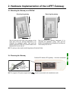
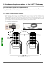
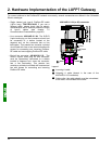
2) Cables:
VW3 A8 306 R•• Modbus cable...................................
(“star” topology / “bus” topology with tap boxes)
Shielded cable with a male RJ45 connector at each
end.
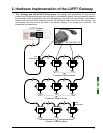
VW3 A68 306 Modbus cable.......................................
(“bus” topology with tap boxes)
Shielded cable with a male RJ45 connector and a
male 15 point SUB-D connector. It is used to connect
a Modbus subscriber (slave or master) to a
TSXSCA62 or TSXCA50 box.
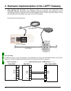
Shielded double twisted pair Modbus cable................
(“bus” topology with branch boxes)
Bare cable (without connectors) used to make up the
main section of the Modbus network. There are three
items available: TSXCSA100 (100 m), TSXCSA200
(200 m), and TSXCSA500 (500 m).
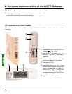
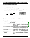
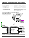
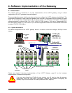
2.6. Connecting the LUFP7 gateway to the Profibus-DP Network
Connect the SUB-D 9-point male plug on
the Profibus-DP connector to the
Profibus-DP plug on the LUFP7 gateway.
Connections are illustrated here:
SUB-D 9-point male
490 NAD 911 04 (or 03)
Modbus
Type
A
Profibus-DP cables
Ref. : TSX PB SCA100
SUB-D
9 points
female
connector
cg
hk
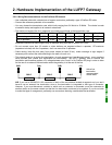
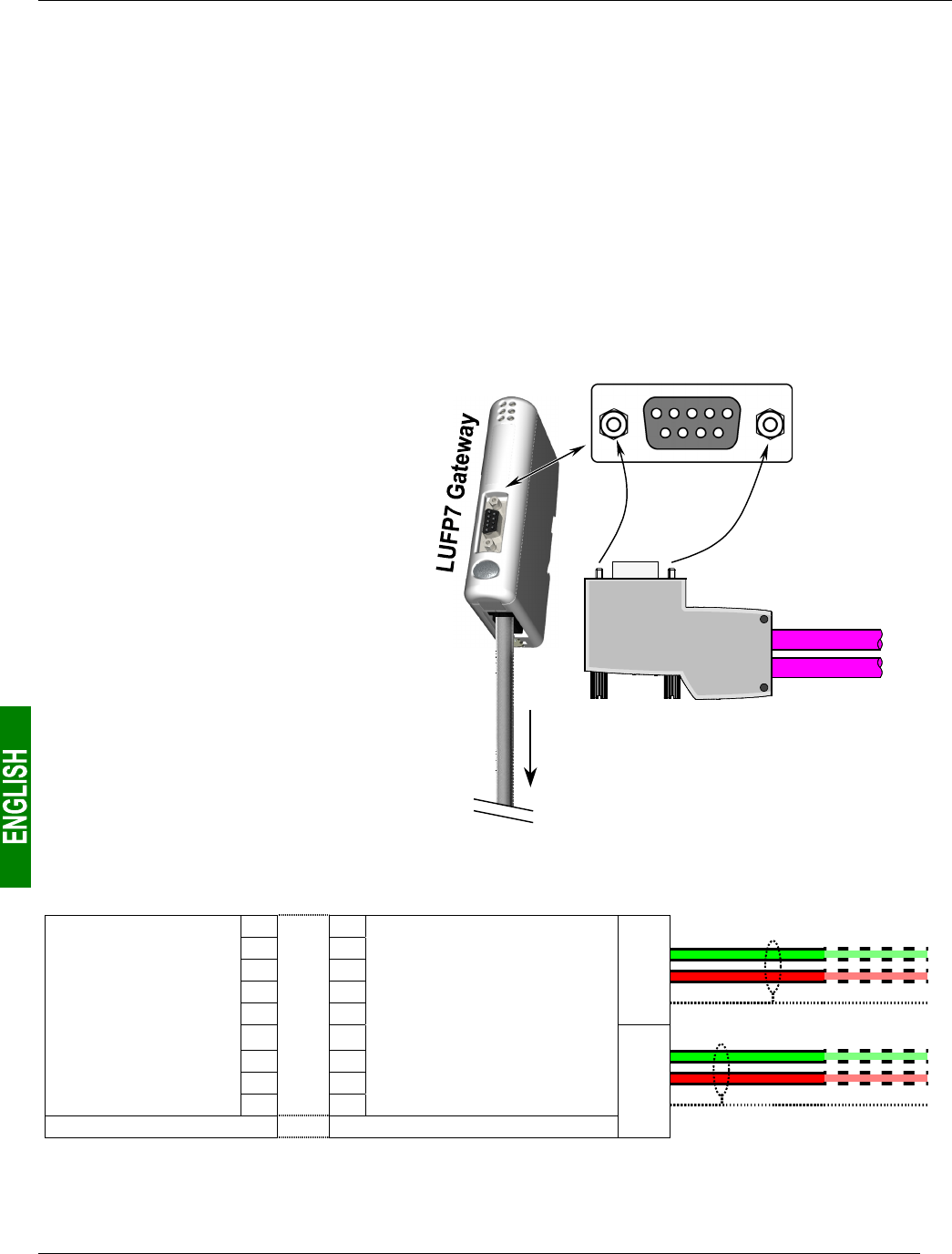
2.6.1. Pin Outs
–
—— LUFP7
p
lu
g
——– — 490 NAD 911 04/03 connector—
—
—T
yp
e A cables ——
9-
p
oint SUB-D female 9-
p
oint SUB-D male
(
TS
X
PB SCA100
)
11 Incomin
g
A cable
2
2
D
(
B
)
3
3 B-line / RxD/TxD +
RTS 4
4Re
q
uest To Send
(
1
)
GND 5
5 GND Réseau
(
2
)
Outgoing A cable
+5V 6
6
+5V Réseau (2)
7
7
D
(
A
)
8
8
A
-line / RxD/TxD –
9
9
Groundin
g
/ Shieldin
g
Shieldin
g
/ Groundin
g
(1) This signal is not mandatory and may be ignored for the LUFP7 gateway.
(2) The “GND” and “+5V” pins are meant to supply the line termination if it is present in the connector being used.