77
6. Configuring the Gateway
Configuration
element
Description
Trigger byte
address
(contd.)
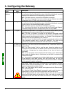
The Profibus-DP master PLC will be able to detect the receipt of a response from a Modbus
slave by comparing the previous value and the current value of the associated counter
(address 16#001E or 16#001F). If there is a
unitary incrementation of this counter, the PLC
may, for example, read all of the data from the response (addresses 16#0013 to 16#0017
or addresses 16#0018 to 16#001D) and allow the transmission of a new query for reading
or writing the value of a parameter (using a “Trigger byte” for the queries). Contrarily to the
counter one can associate to the queries of any command, a response’s “Trigger byte” is a
true modulo 256 counter,
i.e. zero must be managed (… 254, 255, 0, 1, 2 …).
E.g.: With the ATS48, we do not want the response to be event driven. So we will be retaining the default
configuration.
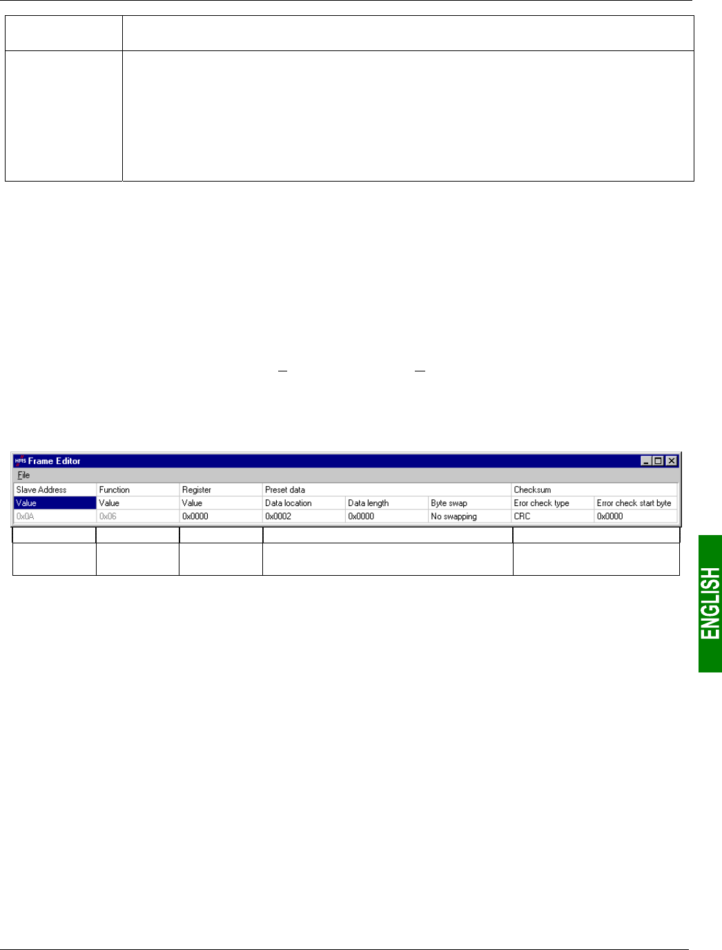
6.11.2.4. Configuring the Content of the Query Frame
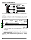
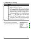
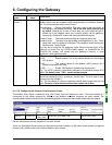
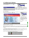
The window shown below is obtained using “Edit Frame” from the “Query” menu. Unlike the tree structure in the
main AbcConf window, this display has the advantage of showing all of the frame’s fields at the same time as well
as their values. The values displayed below correspond to the values assigned by default to the Modbus command
query we have created. The correspondence with the content of the corresponding Modbus frame has been added
underneath this window.
Slave no. Function no.
Word number
(MSB / LSB)
Value of the word (MSB / LSB) CRC16 (LSB / MSB)
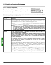
Edit the values which are not greyed out, one after another. There is a description of them below.
The nature of a frame’s fields depends on the Modbus command to which it corresponds. However, a certain
number of these fields are common to all frames, whereas others are common to a number of them. The
description of those shown above is given on the next page, as a part of the example described at the beginning
of the chapter 6.11.2.


