


90
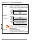
7. Appendix A: Technical Characteristics
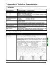
Structure of the LUFP7
gateway’s memory:
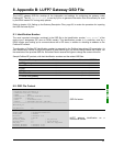
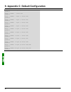
Outputs
• 2 bytes for the activation or inhibition of the downstream network by the gateway
(see chapter 5 Gateway Initialization and Diagnostics, page 37).
• 242 bytes accessible by the Profibus-DP master in the form of output data (see
chapter chapitre 10.2.2 Output Data Memory Area, page 96, for default use of
these output data).
• 268 output bytes inaccessible by the Profibus-DP master due to the maximum
number of output bytes that can be exchanged with the gateway (see
chapter 4.2.6 Editing and Configuring the Gateway, page 29).
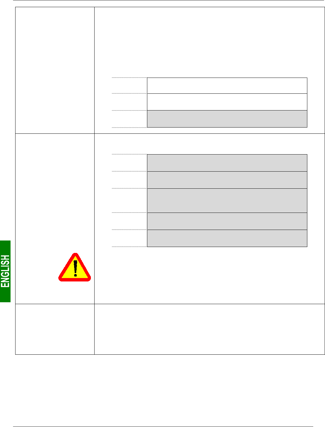
Addresses
Output data area
16#0200
16#0201
Profibus-DP master control word
(except if “Control/Status Byte” = “Disabled”)
16#0202
16#02F3
Outputs accessible by the Profibus-DP master
(242 bytes)
16#02F4
16#03FF
Outputs inaccessible by the Profibus-DP master
(268 bytes)
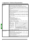
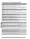
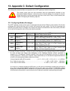
• 1,024 bytes inaccessible through the Profibus-DP master.
Addresses
General data area
Structure of the LUFP7
gateway’s memory:
16#0400
16#051F
Input area reserved for the Mailboxes
(288 bytes)
General data
16#0520
16#063F
Output area reserved for the Mailboxes
(288 bytes)
16#0640
:
16#07BF
Internal area reserved for the management
of the upstream network
(384 bytes; area not used by the LUFP7 gateway)
16#07C0
16#07FD
Internal area reserved for the control registers
(62 bytes / MSB first for 16-bit data)
16#07FE
16#07FF
Gateway status / Profibus-DP master control
(2 bytes)
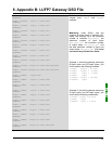
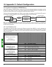
You can use the general data area for Modbus input data (from Modbus
responses) if you do not want the Profibus-DP master to have access to them. In
this case,
always use 16{#4000 as the starting address. If you use multiple times
the same addresses in this area, the corresponding memory locations will be
displayed in red in the “General Area” section of the “Sub-network Monitor”
window (see page 55 for an example). However, this will have no consequences
on the gateway during run-time.
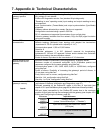
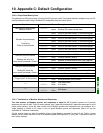
Data transfer order
(swapping)
• Profibus-DP network: MSB first and LSB last.
• Modbus RTU network: MSB first and LSB last.
• LUFP7 gateway MSB stored in the lowest memory address.
→ In most cases, the option which should be chosen for Modbus data stored in
the gateway’s memory is “No swapping”. This option relates to all “Data” fields
for Modbus queries and responses frames.