


89
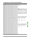
7. Appendix A: Technical Characteristics
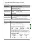
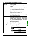
Profibus-DP LUFP7
gateway specifics
(cont'd)
• Profibus-DP address configured using 2 coding wheels (address between 1 and
99); address 0 is not allowed.
• Profibus-DP diagnostics service: Yes (standard 6-byte diagnostic).
• "Resetting to zero" operating mode (input reading and output resetting to zero)
not supported.
• Input synchronisation (Freeze-Mode) and output synchronisation (Sync-Mode)
supported.
• Gateway address allocated by a master: Service not supported.
• Configuration conducted using a specific GSD file.
• DP-V1 extensions not supported (transmission of non-cyclical data).
• Galvanic gateway insulation from the network; D(A) and D(B) signal insulation
using opto-couplers.
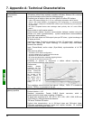
Modbus RTU
characteristics
• Physical media: RS485 serial link
• Network topology: Multipoint linear topology with adapted line terminations
(impedance of 120 Ω in parallel with a capacity of 1 nF)
• Communication speed: 1,200 to 57,600 kbits/s
• Data bits: 8
• Subscriber addresses: 1 to 247. Address 0 reserved for broadcasting.
Addresses 65, 126 and 127 reserved if drivers and/or starters from
Schneider
Electric
are used on the same Modbus network.
• Period of silence: Equivalent to the transmission of 3.5 characters.
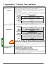
Specific Modbus RTU
features of the LUFP7
gateway
• Maximum number of subscribers (excluding gateway): 8 Modbus slaves.
• Maximum number of commands configured: Up to 50 Modbus queries and
responses configured for the same gateway using AbcConf.
• Communication speed: 1,200, 2,400, 4,800, 9,600, or 19,200 bits/s, configured
using AbcConf.
• Period of silence: Possibility of increasing the gateway’s period of silence, in
10 ms steps, using AbcConf.
• Parity: None, even or uneven, configured using AbcConf.
• Start bits: 1 bit, configuration using AbcConf.
• Stop bits: 1 or 2 bits, configuration using AbcConf.
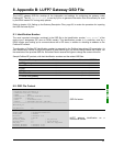
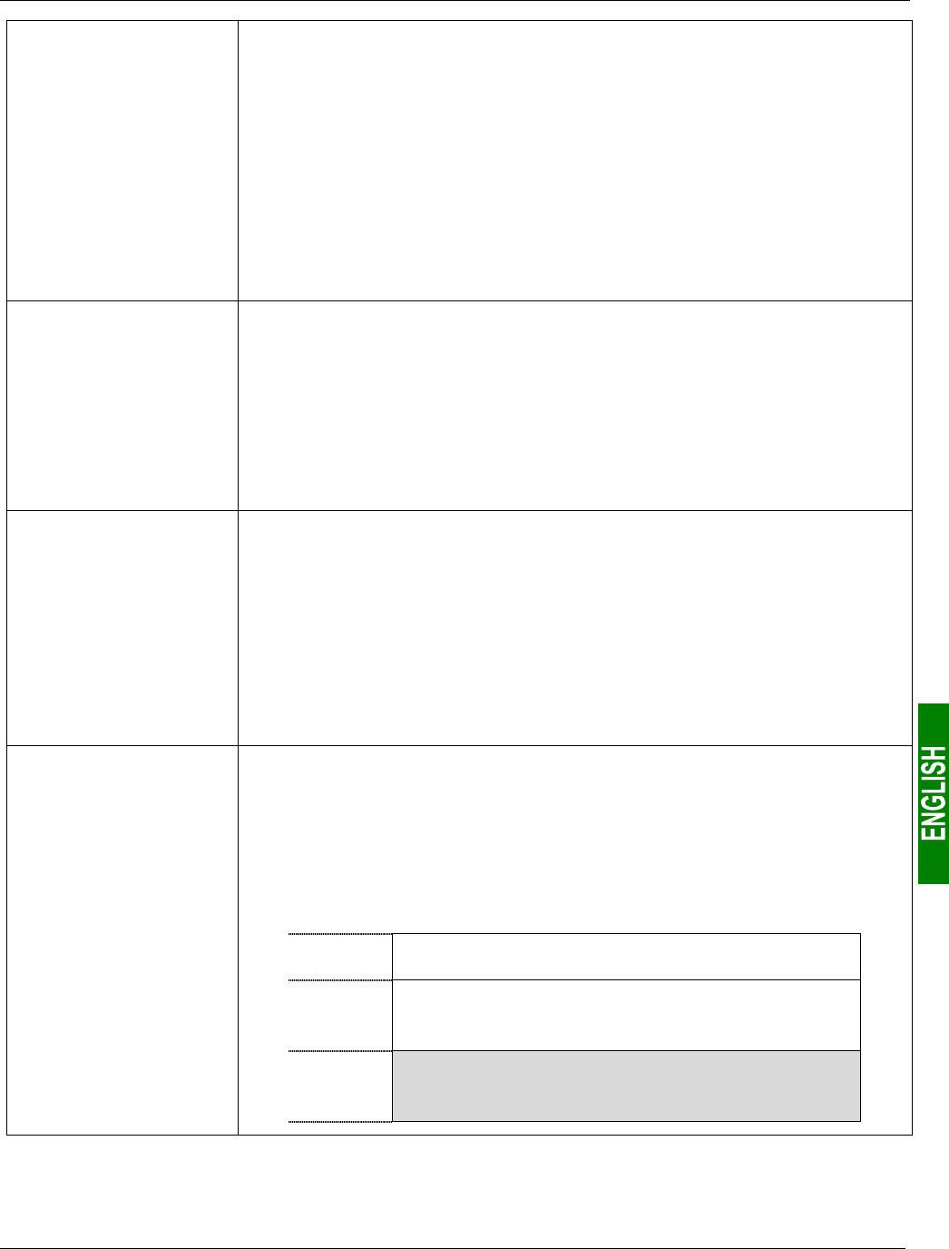
Structure of the LUFP7
gateway’s memory:
Inputs
• 2 bytes for the diagnostics of errors on the downstream network by the gateway
(see chapter 5 Gateway Initialization and Diagnostics, page 37).
• 242 bytes accessible by the Profibus-DP master in the form of input data (see
chapter 10.2.1 Input Data Memory Area, page 95, for default use of these input data).
• 268 input bytes inaccessible by the Profibus-DP master due to the maximum
number of input bytes that can be exchanged with the gateway (see chapter 4.2.6
Editing and Configuring the Gateway, page 29).
Addresses
Input data area
16#0000
16#0001
Gateway status word
(unless “Control/Status Byte” = “Disabled”)
16#0002
:
16#00F3
Inputs accessible by the Profibus-DP master
(242 bytes)
16#00F4
:
16#01FF
Inputs inaccessible by the Profibus-DP master
(268 bytes)