A-4 Sun Netra CP3220 Blade Server User’s Guide • January 2010
A.3 Connectors and Pinouts
A.3.1 Front Panel Connectors
The front panel has the following connectors, see FIGURE 1-1:
■ One 10/100/1000BASE-T Ethernet port (RJ-45)
■ One serial port (RJ-45)
■ Two USB ports
A.3.1.1 Ethernet Port
The Ethernet connector is an RJ-45 connector. The controller autonegotiates to either
10 BASE-T, 100 BASE-T, or 1000 BASE-T.
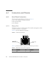
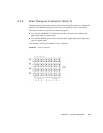
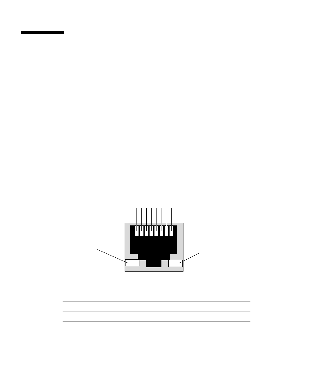
FIGURE A-1 shows the Ethernet port connector.
FIGURE A-1 Ethernet RJ-45 Connector
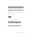
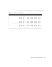
TABLE A-3 provides the eight pin assignments for the Ethernet port connector.
TABLE A-3 Ethernet Port Connector Pin Assignments
Pin Signal Name Pin Signal Name
1 DA+ 5 DC-
1 2 3 4 5 6 7 8
Green LED
Yellow LED
Blink-Activity
Link


