


Appendix A Physical Characteristics A-5
A.3.1.2 USB Ports
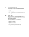
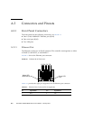
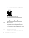
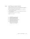
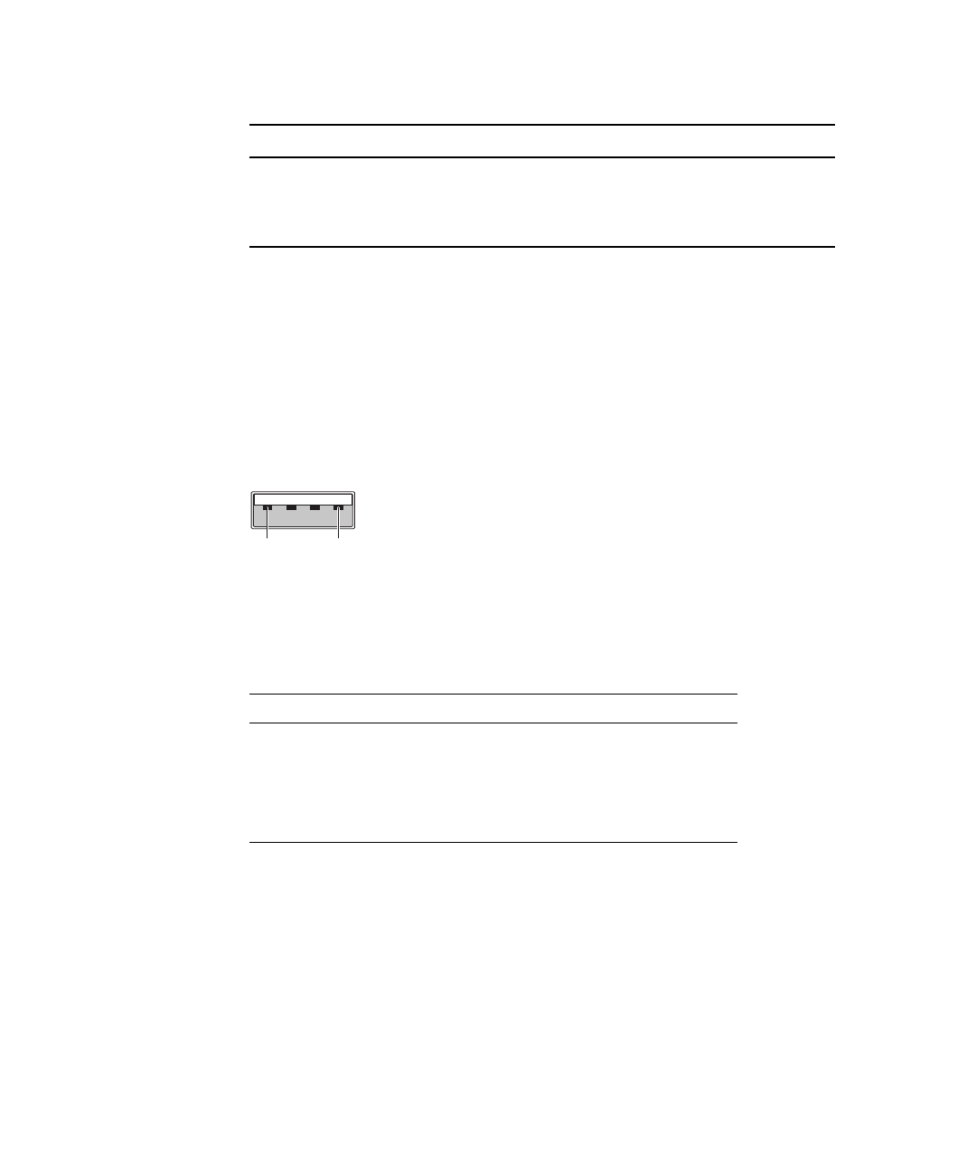
FIGURE A-2 shows the connector pin assignments for both of the front panel USB
ports.
FIGURE A-2 Front Panel USB Connector
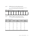
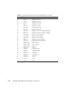
TABLE A-5 lists the USB port connector pin assignments.
2 DA- 6 DB-
3 DB+ 7 DD+
4 DC+ 8 DD-
TABLE A-4 USB Port Pin Assignments
Pin Signal Name Description
1 VCC +5 VDA (500ma)
2 D- Data-
3 D+ Data+
4 GND Ground
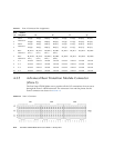
TABLE A-3 Ethernet Port Connector Pin Assignments (Continued)
Pin Signal Name Pin Signal Name
14